 In general, a Pseudowire (PW) is an emulation of a point-to-point connection over a packet-switched network (PSN). To put it simply, PW is an emulated circuit.
The PW is also an industry term for the transport of any frames over an MPLS network using MPLS to encapsulate and LDP as a signaling mechanism. Cisco calls this AToM for Any Transport over MPLS and this is the building block of the Layer 2 VPNs over MPLS [1].
Although PW is defined to run over PSN such IPv4 or IPv6 networks, Layer 2 Tunneling Protocol (L2TPv3) networks, MPLS is now commonly used for this purpose. Therefore, we will focus on the explanation and configuration of PW related to MPLS-based pseudowires.
PW is a connection between two provider edge (PE) devices that connects two attachment circuits (AC) (Figure 1). The AC part carries the customer traffic in native form, e.g., Ethernet frames with/without VLAN tagging (RFC 4448), legacy services such as ATM (RFC 4717, 4816), Frame-Relay (RFC 4619), etc.
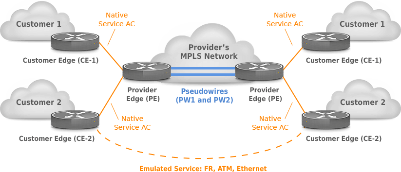
Figure 1 – Pseudowire Emulation (provider) Edge to Edge PWE3 Reference Model (RFC 3916)
Pseudowires can be used to deliver two types of services to end-users:
- Virtual Private LAN Service (VPLS)
- Virtual Private Wire Service (VPWS)
VPLS emulates a LAN over an MPLS network, so different sites share the Ethernet broadcast domain. MPLS tunnel is set up between every pair of PEs (full-mesh).
VPWS is an L2 point-to-point service provisioned by Layer 2 VPN, which delivers the virtual equivalent of a leased line. Any Transport Over MPLS (AToM) is Cisco’s implementation of VPWS for IP/MPLS networks.
Native packets or frames that are received on ingress PE are encapsulated with two MPLS labels (tunnel and VC) and sent across PWs to the egress PE router (Picture 2):
- Tunnel/transport label (top label)
- VC/VPN label (bottom label)
The ingress PE router first pushes the VC label on the frame and then the tunnel label. The MPLS packet is forwarded based on tunnel label hop by hop until it reaches the egress PE. In our case, the tunnel label is number 18 (Figure 2). It is worth saying that when the egress PE router receives an MPLS packet, the tunnel (the topmost) label is already removed by the PE router due to Penultimate-Hop-Popping (PHP) behavior. Therefore, only the VC label is presented within the MPLS packet.
| NOTE: The tunnel label is derived through the Label Distribution Protocol (LDP). |
VC label identifies a particular circuit (PW) in a tunnel and egress AC on the egress PE. This label is on the bottom of the label stack. When the egress PE router receives the packet from Pseudowire, it looks up the VC label in the forwarding information base, removes the VC label (label 21), and forwards the frame to AC.
| NOTE: P routers are completely unaware of customers’ network. They just forward frames based on the top MPLS label. |
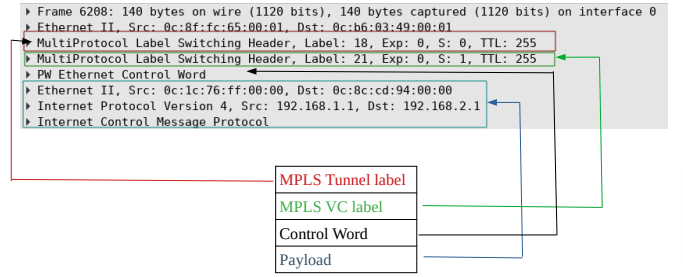
Figure 2 – Pseudowires Encapsulation on Ingress PE (Router PE-1 on Figure 3)
MPLS L2 VPN Configuration
The Layer 2 connection is extended through the service provider’s (SP) MPLS network (routers R2 – R5 (Figure 3). The L2 MPLS VPN tunnel between R2 and R5 bridges two Layer 2 domains: CE1-PE1 and CE2-PE2. The tunnel is identified by the virtual circuit (VC) ID 10 (Picture 4).
| NOTE: There is no layer 3 relationship between CE and PE routers; the connection is the layer 2 type. Therefore, PEs have no IP addresses configured on the interfaces facing CE, and the PE routers are completely transparent to the EIGRP routing protocol configured on CE routers. |
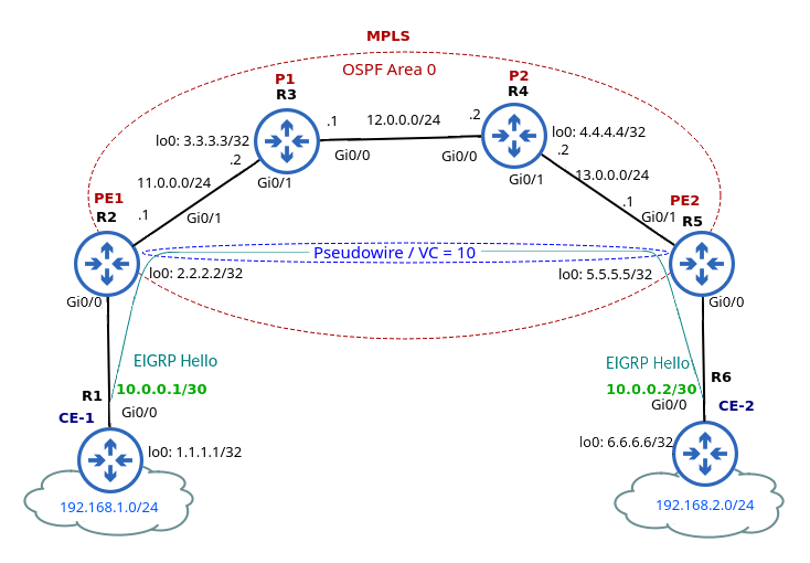
Figure 3 – MPLS Layer 2 VPN
Traffic that is coming through the interface Gi0/0 on R2 is encapsulated and pushed to R5 with two labels (Figure 4).
The bottom (VC) label identifies the tunnel; R2 uses label 21 given by R5 and a local label 16. Similarly, R5 uses the label 16 given by R2. This is because MPLS LSPs are unidirectional by default, so we need two of them in opposite directions to enable bidirectional communication. The top (tunnel) label 18 is to move traffic from R2 to R5.
In terms of CE routers (R1 and R6), they appear to be directly connected by a single L2 circuit. The IP addresses configured on their Gi0/0 interface are assigned from the same subnet 10.0.0.0/30.
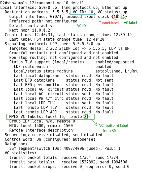
Figure 4 – VC Info for Circuit Transport Over MPLS from the PE-1 Perspective
The routers R1 and R6 are routing peers, and they build their EIGRP peer relationship through the point-to-point L2 VPN tunnel. The peer R6 learns about networks 192.168.1.0/24 and 1.1.1.1/32 from the EIGRP Update message received from R1. Similarly, R1 learns about 192.168.2.0/24 and 6.6.6.6/32 from R6 (Figure 5).
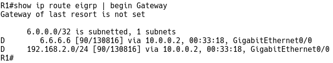
Figure 5 – EIGRP Routes on R1 advertised by R6
PE1 Configuration
Most of the configuration is done on the PE routers. Initial PE configuration includes enabling mpls globally and for the Ethernet interface toward P router, setting up a loopback for OPSF router ID and configuring OSPF for MPLS.
Finally, we will create a new pseudo-class and select mpls encapsulation for the class. Once we create a pseudowire class, we will use the xconnect command pointing to the IP address of the remote PE router (R5) along with VC ID (10) and the already configured pseudo class for the interface connected to the CE router (Gi0/0).
pseudowire-class R1_L2-R6_L2
 encapsulation mpls

interface Loopback0
 ip address 2.2.2.2 255.255.255.255

interface GigabitEthernet0/0
 no ip address
 xconnect 5.5.5.5 10 encapsulation mpls pw-class R1_L2-R6_L2

interface GigabitEthernet0/1
 ip address 11.0.0.1 255.255.255.0
 mpls ip

router ospf 1
 network 2.2.2.2 0.0.0.0 area 0
 network 11.0.0.0 0.0.0.255 area 0
| NOTE: In the case of L2TPv3, encapsulation l2tpv3 is used under the pseudowire-class command. |
P Configuration
Configuration of MPLS core is pretty straightforward; we only enable MPLS switching on the interfaces toward PE and P routers and OSPF. Make sure that LDP router ID is forced to a loopback interface.
interface Loopback0
 ip address 3.3.3.3 255.255.255.255

interface GigabitEthernet0/0
 ip address 12.0.0.1 255.255.255.0
 mpls ip

interface GigabitEthernet0/1
 ip address 11.0.0.2 255.255.255.0
 mpls ip

router ospf 1
 network 3.3.3.3 0.0.0.0 area 0
 network 11.0.0.0 0.0.0.255 area 0
 network 12.0.0.0 0.0.0.255 area 0
We can test the PW section of AToM VC with MPLS LSP ping from the R2 router (Figure 6).
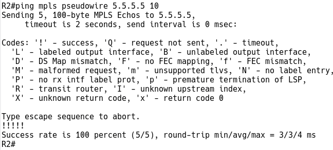
Figure 6 – MPLS LSP Ping to Test PW Section of AToM
CE1 Configuration
Customer devices require configuration of the loopback interface so that EIGRP can select the IP on that interface as the router-id and configuration of EIGRP itself.
Cinterface Loopback0
 ip address 1.1.1.1 255.255.255.255

interface Loopback1
 ip address 192.168.1.1 255.255.255.0

interface GigabitEthernet0/0
 ip address 10.0.0.1 255.255.255.252

router eigrp 1
 network 1.1.1.1 0.0.0.0
 network 10.0.0.0 0.0.0.3
 network 192.168.1.0
Finally, we will test the emulated circuit between CE devices with the ping command (Figure 7).
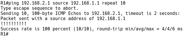
Figure 7 – Ping to Test Emulated Circuit
Conclusion
If a customer is attached to a Service Provider with an existing MPLS backbone, AToM may be a good L2 VPN option to transfer traffic between the customer’s endpoints. Service providers do not need to invest in separate Layer 2 devices.
However, where there is no MPLS-enabled network, L2TPv3 can be used to provide L2 VPN services.
Both options support Ethernet, PP, HDLC, TDM, FR, and ATM technologies.