 In order to get end-to-end visibility for applications, we need complete topology data from IGP domains. One approach is to set up a central SDN controller as an IGP listener in the network, passively join it to IGP and listen for link-state advertisements (LSAs). However, this solution is not scalable when there is a need to consolidate topology views from networks spanning thousands of routers in multiple IGP domains, often located in different geographic areas. The controller needs to hear all IGP updates, so it needs a direct link to each area or domain. In this case, we need to build thousands of GRE tunnels between a controller and routes to establish OSPF adjacency. There also appears a computational problem because the controller spends its time processing all IGP updates. In addition, both IS-IS and OSPF must be supported.
Another fact which speaks against allowing an external application to IGP domains is that it is difficult to control what information is available to the application. In addition, a controller can also influence routing, injecting information into the Link-state database (LSDB). BGP with Link State (BGP-LS) can solve all the problems we have already mentioned, carrying the link-state information and making it accessible to external applications. In other words, BGP-LS is not used as a BGP routing protocol calculating link state and making forwarding decisions. It is only used to carry link-state information from the IGP routing protocols. Some advantages of the BGP-LS are obvious, while others are not. Let’s dive into the topic a little bit deeper.
BGP scales very well when millions of prefixes need to be transported; thus, it can also scale IGP link-state information. In addition, BGP is widely deployed and is already part of the service providers’ infrastructure, so deploying a new feature is not a big problem. It is easy to set up a BGP session between an SDN controller and the network. BGP is the only protocol the controller needs to support; thus, there is no need to support both IGPs. In addition, BGP sessions between the controller and the BGP speakers can be multihop; no direct connectivity is required. Finally, BGP-LS is a one-way information exchange; the controller retrieves the topology information but does not influence routing. Last but not least, BGP has extensive policy mechanisms to control the exchange of information and protect the network. Therefore, operators can control what information will be available to the application.
BGP-LS is defined in the RFC7752. This specification contains two parts:
- new BGP link-state Network Layer Reachability Information – BGP-LS NLRI defines three objects – links, nodes, and prefixes. We can reconstruct IGP topology with the combination of Node and Link objects. IP prefix objects provide network reachability information.
- new BGP path attribute (BGP-LS attribute) that encodes properties of link, node, and prefix objects, such as IGP metric (Picture 1)
| NOTE: Information carried by the new link-state NLRI and BGP-LS path attribute is represented in an IGP neutral way. |
BGP Update message containing MP_REACH_NLRI and BGP-LS attributes is depicted in Picture 1. Notice the BGP-LS NLRI inside MP_REACH_NLRI. The AFI 16388 and SAFI 71 are used for non-VPN links, node, and prefix information.
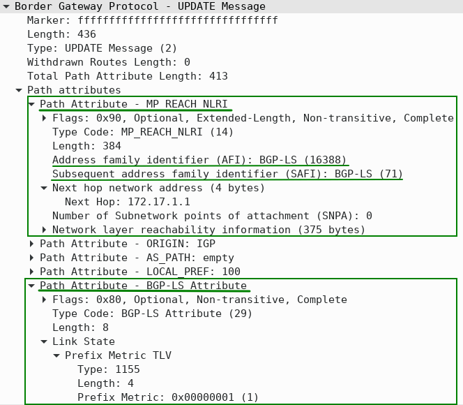
Figure 1 – Path Attribute MP_REACH_NLRI with AFI 16388 and SAFI71 and Path Attribute BGP-LS Inside BGP UPDATE Message
The more granular view of the BGP update Message is depicted in Picture 2. There are four types of BGP-LS NLRI:
- Type 1 – Node NLRI
- Type 2 – Link NLRI
- Type 3 – IPv4 Topology prefix NLRI
- Type 4 – IPv6 Topology prefix NLRI
| NOTE: Each link-state NLRI describes either a node, link, or a prefix (IPv4 or IPv6). |
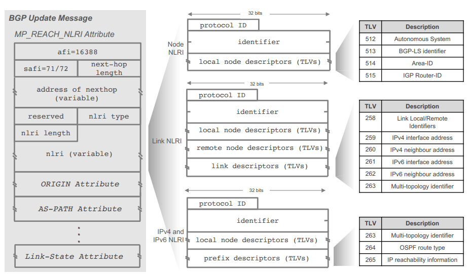
Figure 2 – BGP UPDATE Message (Source)
Let’s look at the network topology to help us understand how BGP-LS works. OSPF runs on routers IOS-XR-1 through 3. Identical database Link-state database (LSDB) is on all nodes in area 0. The LSDB contains the router’s IP address and link attributes of the router:
- neighbor router identifier
- local interface IP address
- remote interface IP address
- IP subnet address of the link
- IGP link metric
All routers in OSPF area 0 share the same topology, so, at minimum, only a single BGP-LS speaker is required in area 0. Router IOS-XR1 (AS100) participating in the IGP obtains info from IGP LSDB and distributes IGP topology information (see above) to the controller using BGP NLRI. The controller is a consumer of the topology information and peers with IOS-XR-1.
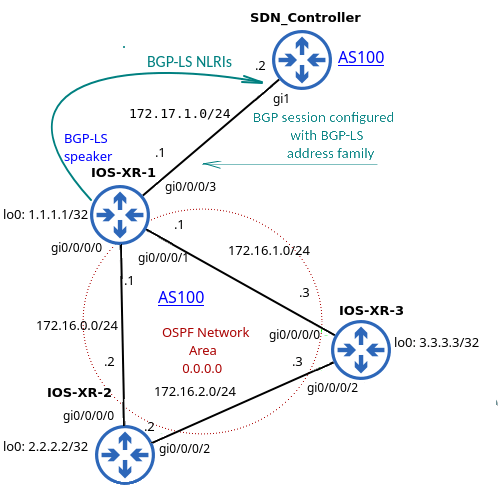
Figure 3 – Simple Network Topology with Two BGP-LS Speakers in AS100 and Single OSPF Area 0
The relevant configuration for OSPF and BGP-LS is depicted in Picture 4. We need to configure distribute bgp-ls (IOS-XR) or distribute link-state (IOS-XE) under OSPF configuration on a Cisco router to enable IGP to BGP link-state information distribution. As for BGP, we need to enable the link-state address family with the command address-family link-state link-state to advertise bgp-ls routes between the router IOS-XR-1 and the SDN controller. The routers signal each other the ability to exchange link-state NLRI with Capabilities Advertisement (AFI 16388 / SAFI71) within BGP Open Message (Picture 5).
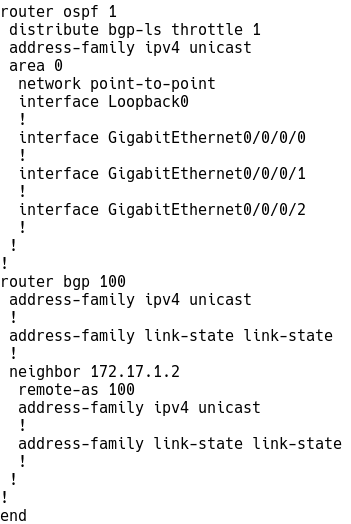
Figure 4 – OSPF and BGP-LS Configuration on IOS-XR-1
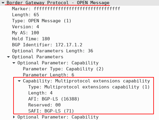
Figure 5 – BGP Open Message with BGP-LS Capability
The output from the BGP-LS database captured on the SDN controller is depicted in Picture 6.
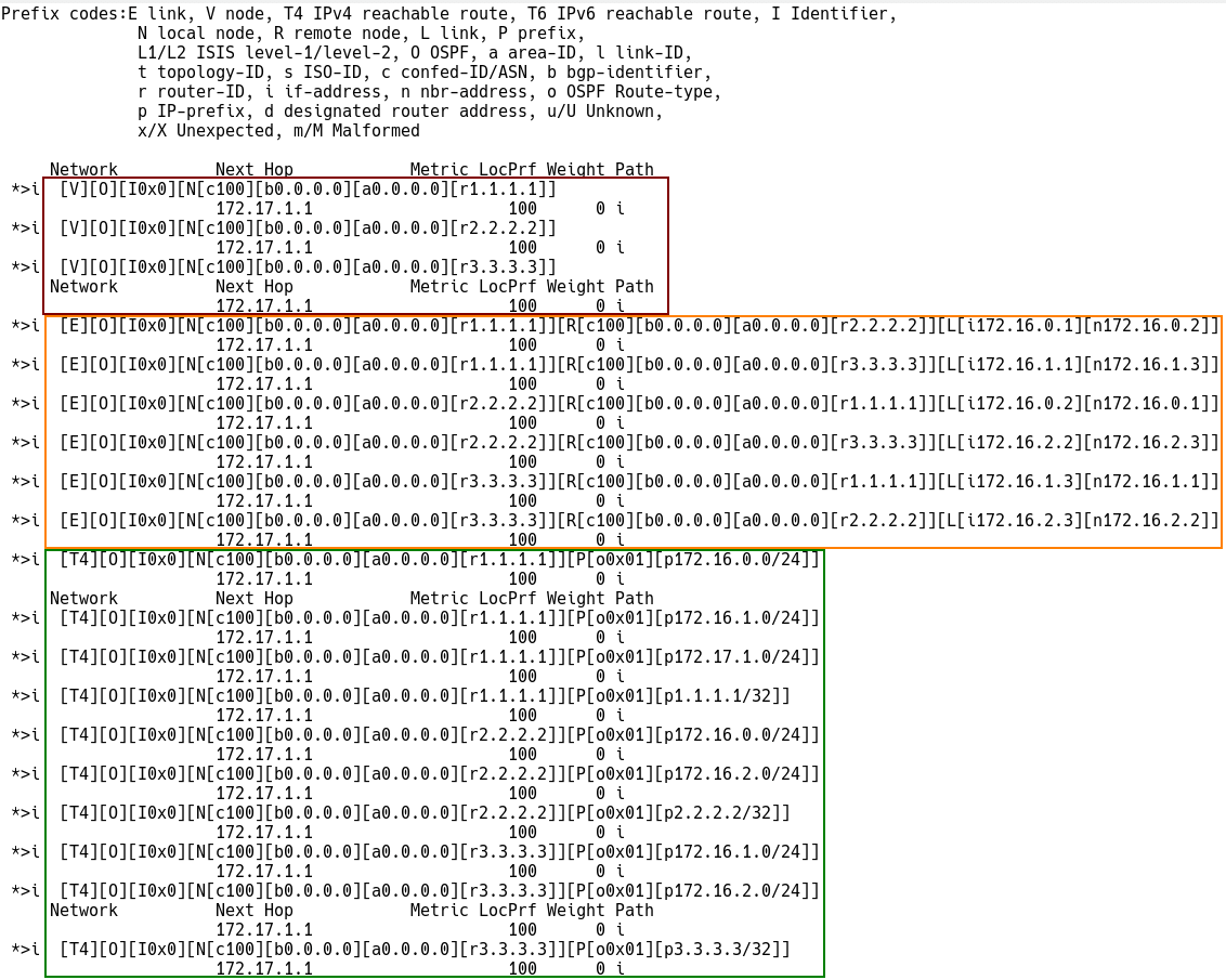
Figure 6 – The Output from BGP-LS Database on SDN Controller
As our network topology consists of three IGP nodes, there are three Node prefixes (Type-1) with router IDs – 1.1.1.1, 2.2.2.2, and 3.3.3.3 describing the nodes. The next-hop IP address is 172.17.1.1 for all node prefixes.
Example of Node Descriptor Prefix:
*> [V][O][I0x0][N[c100][b0.0.0.0][a0.0.0.0][r1.1.1.1]]
172.17.1.1
[V] – Node Descriptor Route
[O] – OSPF Node
[b0.0.0.0] – bgp identifier
[a0.0.0.0] – area ID
[r1.1.1.1]] – router ID
There are three point-to-point links, so we have six (3×2) Link descriptors prefixes (Type 2) to describe all the links. Each descriptor represents a half-link. The BGP-LS attribute provides additional information about the link, such as IGP metric, TE-metric, Bandwidth, etc.
The Link Descriptor Prefix below is depicted in Picture 7. The IGP metric inside the BGP-LS attribute is 1. The prefix describes a half-link between the local node 1.1.1.1 and the remote node 2.2.2.2.
[E][O][I0x0][N[c100][b0.0.0.0][a0.0.0.0][r1.1.1.1]][R[c100][b0.0.0.0][a0.0.0.0][r2.2.2.2]][L[i172.16.0.1][n172.16.0.2]]
[E] – Link Descriptor Route
[O] – OSPF Node
[N[c100][b0.0.0.0][a0.0.0.0][r1.1.1.1] – Local node router-ID 1.1.1.1.
[R[c100][b0.0.0.0][a0.0.0.0][r2.2.2.2]] – Remote node router-ID 2.2.2.2
[L[i172.16.0.1][n172.16.0.2]] – local link address is 172.16.0.1 and the remote end IP is 172.16.0.2
Check the metric for the Link-state prefix below:
Controller# show bgp link-state link-state NLRI [E][O][I0x0][N[c100][b0.0.0.0][a0.0.0.0][r1.1.1.1]][R[c100][b0.0.0.0][a0.0.0.0][r2.2.2.2]][L[i172.16.0.1][n172.16.0.2]]
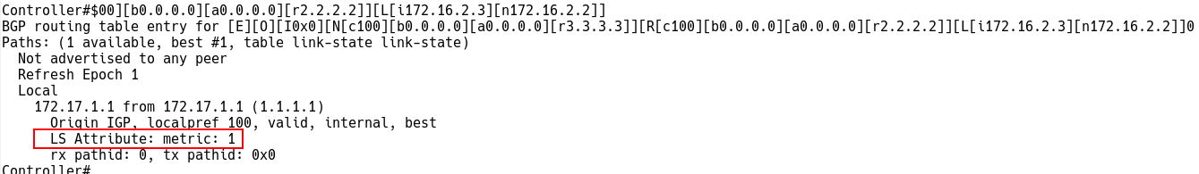
Figure 7 – Checking Link Descriptor Route on Controller
There are ten prefixes in our topology, so there are ten Prefix descriptors (Type-3 for IPv4) advertised by a particular Node.
IOS-XR-1: 1.1.1.1/32, 172.17.1.0/24, 172.16.0.0/24 and 172.16.1.0/24
IOS-XR-2: 2.2.2.2/32, 172.16.0.0/24, 172.16.2.0/24
IOS-XR-3: 3.3.3.3/24, 172.16.1.0/24, 172.16.2.0/24
[T4][O][I0x0][N[c100][b0.0.0.0][a0.0.0.0][r1.1.1.1]][P[o0x01][p172.16.1.0/24]]
[T] – Prefix Descriptor Route
[O] – OSPF Node
[N[c100][b0.0.0.0][a0.0.0.0][r1.1.1.1]][P[o0x01][p172.16.1.0/24]] – Prefix 172.16.1.0/24 is advertised by the local node 1.1.1.1.
Captured IPv4 Topology Prefix that describes the prefix 172.16.1.0/24 advertised by 1.1.1.1 is depicted in Picture 8.
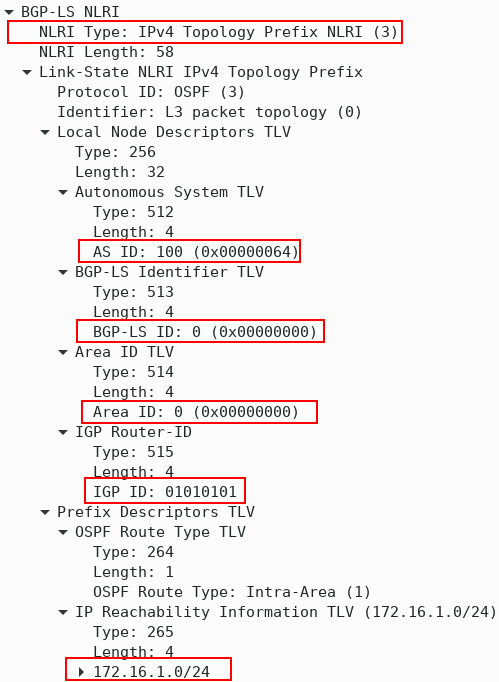
Figure 8 – IPv4 Topology Prefix (Type-3) BGP-LS NLRI
Conclusion
BGP-LS creates an abstract view of the IGP and scales IGP very well. It is ideal for scenarios where there is no other way of transferring IGP topology, and the SDN application does not need real-time data. BGP speaker must not accept updates from the consumer peer, and the operator should use a mechanism to protect the BGP speaker against a DDoS attack from consumers. Network operators must also ensure that only trusted customers are configured to retrieve link-state and TE information, as the customer gets a complete view of the IGP network topology.