What is VPN?
Virtual Private Networks (VPN) are designed to provide users with the private networks capabilities over a shared infrastructure. They connect remote sites and provide the same level of privacy as private networks do. IP Security (IPSec) VPNs provide data confidentiality through the use of encryption, authenticity through the use of message authentication, data integrity via a hashing algorithm and the anti-replay through the use of the authenticated sequence numbers. IPSec VPNs are often used in Hub-Spoke designs where the number of links equals n-1. However, in a fully meshed topology, the number of links grows substantially, as per the formula n*(n-1)/2. Customer routers peer with each other, thus adding a new VPN site requires a configuration change on all the existing sites. Obviously, scalability issue is a major drawback of IPSec VPNs, as with a large number of sites the configuration overhead increases drastically.
Benefits of BGP / MPLS Layer 3 VPN
BGP / MPLS Layer 3 VPNs represent an alternative to IPSec VPNs when supporting complex topologies. They solve the scalability issue of conventional IPSec VPNs deployed in a full-mesh model, reducing the configuration overhead while interconnecting many sites. Adding a new site to VPNs requires a single change on the Provider Edge (PE) device that connects the customer router. Customer Edge (CE) router peers with service provider’s PE router using the IGP or eBGP, exchanging layer 3 routing information with the PE router. However, the CE router has no VPN awareness. A VPN is formed between PE routers that run the Multiprotocol Extension for BGP-4 (MP-BGP), RFC 4760. MP-BGP is used for distributing customer prefixes within the provider’s network. Customer’s data is switched in the service provider’s Multiprotocol Label Switching (MPLS) network based on labels. Traffic follows through a predetermined label-switched path (LSP), which is an unidirectional tunnel between a pair of the PE routers.
| Note: The combination of VRF, MPLS and MP-BGP ensures that the traffic from one VPN does not leak into the other VPN, while the same private IP address (RFC 1918) space can be used for the VPN sites. |
Using MPLS for forwarding packets in the provider’s backbone network brings another benefit in the form of traffic engineering (TE). A Customer’s traffic can be moved over the underutilized path in a provider’s MPLS network or it can be prioritized based on the service. Thanks to TE, a non-congested path with higher latency can be preferred over the congested path with lower latency. Classic IGP such as OSPF uses non TE routing. In case of OSPF, cost per link is used as metric for the SPF algorithm to find the shortest path. In this case, the best paths through the service provider cores might be used heavily while other, redundant paths, would be underutilized. Changing the cost may help but it can affect the whole network at the same time.
BGP / MPLS Layer 3 VPN Infrastructure
Picture 1 shows the BGP / MPLS Layer 3 VPN infrastructure. The function of each device in the network is explained further in the article.
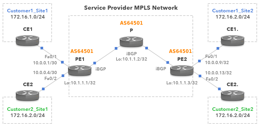
Picture 1: BGP/MPLS Layer 3 VPNs Infrastructure
Customer Edge (CE) router sits at the edge of a customer site and is typically owned by the customer. Customer router advertises the route to the PE router via a routing protocol. The PE router installs the received route in a VRF along with an appropriate VPN MPLS label.
Provider Edge (PE) router sits at the edge of the provider’s network, connecting one or several CE routers. There are multiple forwarding routing tables running on the PE routers per site, also known as VPN Routing and Forwarding Tables (VRFs). The customer-facing interfaces are assigned to VRFs with each site being configured with its own VRF. PE router assigns the Route Distinguisher (RD) to every VRF either in the form of : or :. Adding the 8-Byte RD, PE router converts customer’s routes into the 12-byte VPN-IPv4 (aka VPNv4) addresses. This ensures that the customers’ prefixes are unique in the provider’s network even though the customers use overlapping private addresses.
In the configuration example below, two customers are connected to the PE router. Service provider has defined two VRF instances, one for each customer. Provider uses BGP AS number 64501. The route-target specifies how routes are imported and exported from the VRF. For instance, PE1 exports the route 172.16.1.0/24 from VRF Customer1, assigning it route-target 64501:1. Router PE2 installs this route into the VRF Customer1 as it has configured RT 64501:1 (not shown). The keyword both means the import and export routes from/to the VRF. Accordingly, Router PE1 exports the route 172.16.2.0/24 from VRF Customer2, assigning it route-target 64501:2. The router PE2 then installs the route 172.16.2.0/24 into VRF Customer2 as it has configured RT 64501:2.
PE1(config)# ip vrf Customer1
PE1(config-vrf)# rd 64501:1
PE1(config-vrf)# route-target both 64501:1
PE1(config-vrf)# ip vrf Customer2
PE1(config-vrf)# rd 64501:2
PE1(config-vrf)# route-target both 64501:2
| Note: VPN-IPv4 addresses are used only in provider’s network. Translation from IP to VPN-IPv4 occurs only on the PE router. PE routers maintain the VPN routes, however they only need to know routes for VPNs that have the attached sites. |
The commands below assign customer-facing interfaces on PE1 router to particular VRFs.
PE1(config)# interface f0/1
PE1(config-if)# ip vrf forwarding Customer1
PE1(config-if)# ip address 10.0.0.1 255.255.255.252
PE1(config-if)# interface f0/2
PE1(config-if)# ip vrf forwarding Customer2
PE1(config-if)# ip address 10.0.0.5 255.255.255.252
PE router marks the VPN-IPv4 routes with extended community and advertises them via MP-BGP. Multiprotocol BGP allows BGP to support address families other than IPv4 such as VPN-IPv4. All PE routers receive routes via BGP and they filter them based on the VPN extended community.
PE1(config)# router bgp 64501
PE1(config-router)# neighbor 10.1.1.3 remote-as 64501
PE1(config-router)# neighbor 10.1.1.3 update-source loopback 0
PE1(config-router)# address-family vpnv4
PE1(config-router-af)# neighbor 10.1.1.3 activate
Ingress PE1 router is the Label Edge Router (LER) that performs the push of the VPN label to MPLS header for customer traffic. VPN label is the inner label and it is kept untouched by the P routers. The label is used to identify a correct next-hop on remote PE router. In other words, PE routers use VPN labels to direct data packets to the correct CE device. The remote PE router receives a packet containing a VPN label, performs a pop of the label and forwards customer traffic to the correct CE router.
| Note: VPN-IPv4 routes along with the inner VPN label and route-target are distributed by MP-BGP between the PE routers. The outer LSP label is learned via the LDP (Label Distribution Protocol). |
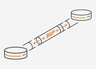
Picture 2: MP-BGP Update Message
Along with the inner VPN label, PE router stacks IP packet with the outer LSP (Label Switch Path) label. The LSP label has only local significance and gets swapped with a new label by every P router along the path. The last P router is a penultimate router for the LSP. It performs a pop of the LSP label and switches customer traffic to the PE router with the inner (VPN) label only.

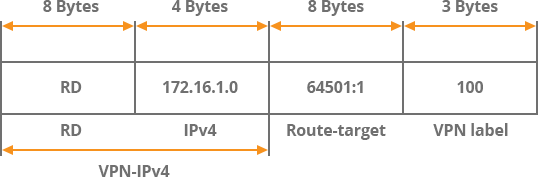
Picture 3: MPLS VPN Packet Structure
Provider (P) router is a Label Switching Router (LSR), as it is not connected to any CE routers. P routers do not contain the VPNv4 routes, but only routes to the other P and PE routers. P routers examine only the topmost (outer) LSP label and swap the outer label with a new LSP label before forwarding the packet. The forwarding of the packet is done based on the content of the LSP header which avoids the IP longest prefix match on each P router.
| Note: To establish the BGP adjacency, PE an P routers are running IGP such as OSPF within the provider network. |
Conclusion:
BGP / MPLS VPNs are typically seen in enterprise environments. They are configured by the service providers, requiring no VPN related configuration on customer routers. BGP / MPLS VPNs can be easily used to provide a fully meshed network architecture. Rather than relying on encryption algorithm, privacy is achieved by defining a single path within a provider’s network. Routing separation is achieved by assigning the customer router to a separate VRF on the PE routers. Customer address separation is achieved by creating unique VPNv4 routes. These mechanisms are accomplished by the integration of the MP-BGP and MPLS technology, which allows users to maintain the separation of traffic from multiple subscriber networks as the traffic is switched through a single shared core.
Check out the BGP/MPLS Layer 3 VPNs Practical Configuration article to learn more.