 In our previous blog article we’ve discussed the benefits and the fundamental principles of BGP/MPLS L3 VPNs. We have covered the definition of the basic terms such as the Route Distinguisher (RD), the Route Target (RT) and the VPN-IPv4 prefix. This post goes further. We are going to support the theory behind the BGP/MPLS L3 VPNs with a practical configuration.
Our lab network consists of PE1, PE2 and P routers, which are part of a service provider’s MPLS network. There are two remote sites: 1 (with CustomerA_Site1 and CustomerB_Site1) and 2 (with CustomerA_Site2 and CustomerB_Site2) both connected to a service provider’s MPLS network. Our goal is to interconnect the remote customer sites so that they can communicate privately over a shared medium. This is where BGP/MPLS VPNs come in handy, separating traffic from both customers, using a combination of the VRF, MPLS and MP-BGP.
The customers use private addresses inside their routing domains, which overlap each other. For instance, both customers use the same prefix 172.16.1.0/24 for site 1 and 172.16.2.0/24 for site 2.
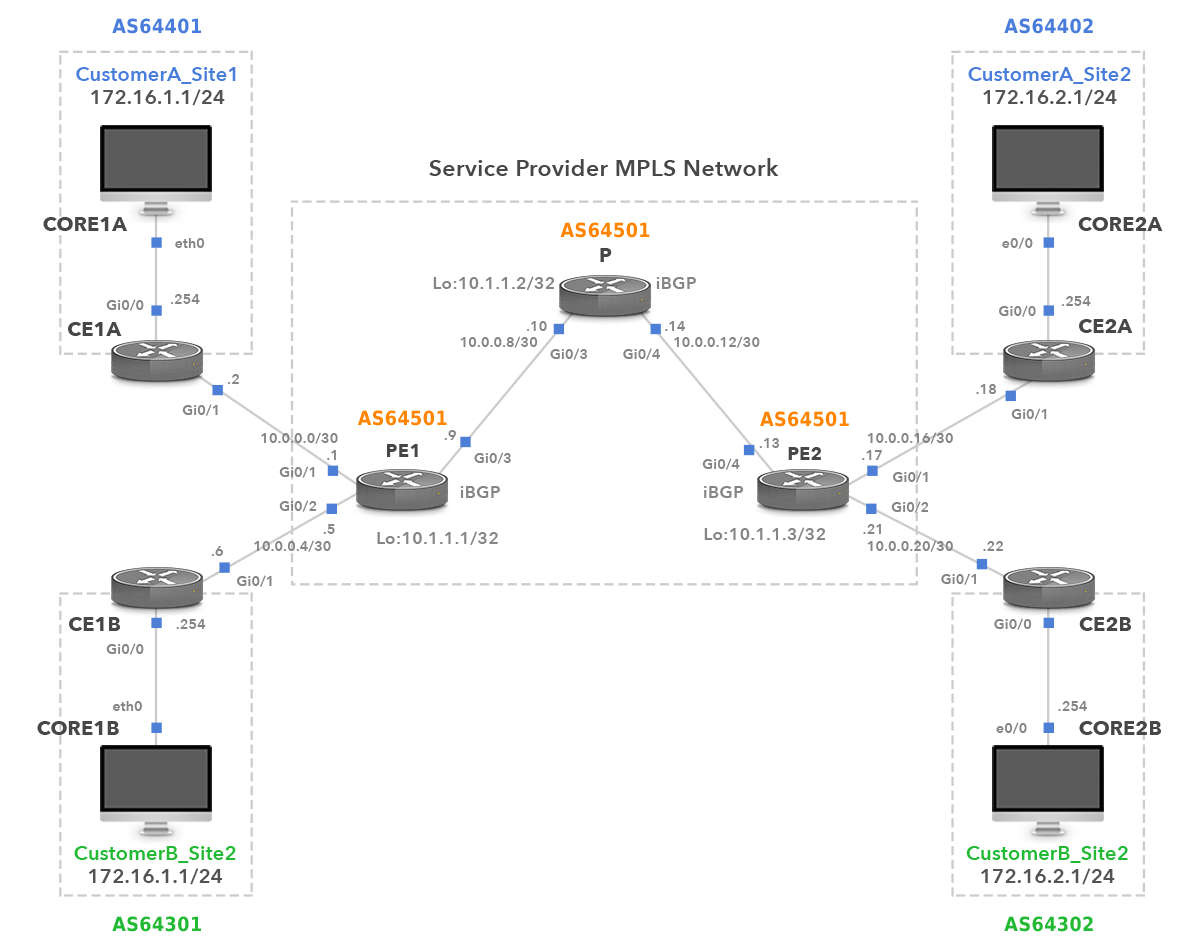
Picture 1: Network Topology
IGP Configuration on P and PE routers
First, we will configure the IGP protocol among all P and PE routers to support LDP and BGP adjacencies within the provider network. Even IGP or static routes might be a choice. We can configure EIGRP, as all routers in our example are from Cisco.
PE1(config)# router eigrp 1
PE1(config-router)# network 10.0.0.8 0.0.0.3
PE1(config-router)# network 10.1.1.1 0.0.0.0

P(config)# router eigrp 1
P(config-router)# network 10.0.0.8 0.0.0.3
P(config-router)# network 10.0.0.12 0.0.0.3
P(config-router)# network 10.1.1.2 0.0.0.0

PE2(config)# router eigrp 1
PE2(config-router)# network 10.0.0.12 0.0.0.3
PE2(config-router)# network 10.1.1.3 0.0.0.0
eBGP Configuration On Customer Routers
Now let’s configure the eBGP adjacency between CE and PE routers. BGP AS numbers at each customer site must be unique and differ from the provider’s ASN. For instance, the customer A BGP AS number is 64401 at site 1 and ASN 64402 at site 2. We also advertise each customers’ subnet from CE to PE router with the following network commands:
CE1A(config)# router bgp 64401
CE1A(config-router)# neighbor 10.0.0.1 remote-as 64501
CE1A(config-router)# network 172.16.1.0 mask 255.255.255.0

CE2A(config)# router bgp 64402
CE2A(config-router)# neighbor 10.0.0.17 remote-as 64501
CE2A(config-router)# network 172.16.2.0 mask 255.255.255.0

CE1B(config)# router bgp 64301
CE1B(config-router)# neighbor 10.0.0.5 remote-as 64501
CE1B(config-router)# network 172.16.1.0 mask 255.255.255.0

CE2B(config)# router bgp 64302
CE2B(config-router)# neighbor 10.0.0.21 remote-as 64501
CE2B(config-router)# network 172.16.2.0 mask 255.255.255.0
Configuring MP-BGP on PE Routers
Multiprotocol BGP is explained in RFC 4760. It defines the extensions to BGP-4 to enable it to carry the routing information for multiple Network Layer protocols (e.g., IPv6, L3VPN). Therefore, we will configure the MP-BGP to distribute customers’ prefixes. The extensions are backward compatible. A router that supports the extensions can interoperate with a router that doesn’t support the extensions.
iBGP neigborship is formed between the PE routers, using ASN 64501. No BGP is configured on router P.
PE1(config)# router bgp 64501
PE1(config-router)# neighbor 10.1.1.3 remote-as 64501
PE1(config-router)# neighbor 10.1.1.3 update-source lo0
PE1(config-router)# address-family vpnv4
PE1(config-router-af)# neighbor 10.1.1.3 activate
PE1(config-router-af)# exit
| Note: The command neighbor 10.1.1.3 send-community extended is automatically configured under the address-family vpnv4 section. |
PE2(config)# router bgp 64501
PE2(config-router)# neighbor 10.1.1.1 remote-as 64501
PE2(config-router)# neighbor 10.1.1.1 update-source lo0
PE2(config-router)# address-family vpnv4
PE2(config-router-af) # neighbor 10.1.1.1 activate
PE2(config-router-af)# exit
| Note: The command neighbor 10.1.1.1 send-community extended is automatically configured under the address-family vpnv4 section. |
Enable MPLS on PE and P Routers
We need to enable MPLS in a provider’s network. Customers’ data are then switched in the MPLS network based on the outer (LSP) label. We will enable MPLS on a provider’s P router and on PE routers.
PE1(config)# interface GigabitEthernet 0/3
PE1(config-if)# mpls ip

P(config)# interface GigabitEthernet 0/3
P(config-if)# mpls ip
P(config)# interface GigabitEthernet 0/4
P(config-if)# mpls ip

PE2(config)# interface GigabitEthernet 0/4
PE2(config-if)# mpls ip
Create and Assign VRFs
Customers’ forwarding tables are separated by using the VPN routing and forwarding table (VRF) concept on the PE router. One VRF is configured on the PE router for each customer. The Router’s PE interface that connects CE router to provider’s MPLS network is then assigned to the customer VRF.
Route distinguisher is added on the PE router to customer’s prefix to distinguish the same prefix and mask in a different VRF. For instance, PE1 router announces prefixes RD1:172.16.10/24 and RD2:172.16.1.0/24 along with VPN label to PE2 router inside the BGP update message. The RD is used to distinguish the prefixes and it has no impact how the routes are installed into the VRFs.

The route target is an extended community attribute used for the import/export of VPN routes. For instance, a VPN prefix 172.16.1.0/24 sent from PE1 to PE2 inside of the MP-BGP update message and carrying the route-target 64501:1 is imported into VRF Customer A on PE2.
PE1(config)# ip vrf CustomerA
PE1(config-vrf)# rd 64501:1
PE1(config-vrf)# route-target both 64501:1
| Note: the commands route-target export 64501:1 and route-target import 64501:1 are automatically configured under vrf configuration. |
PE1(config-vrf)# ip vrf CustomerB
PE1(config-vrf)# rd 64501:2
PE1(config-vrf)# route-target both 64501:2
| Note: the commands route-target export 64501:2 and route-target import 64501:2 are automatically configured under vrf configuration. |
Now we need to assign L3 interfaces to customer VRF.
PE1(config)# interface gigabitEthernet 0/1
PE1(config-if)# ip vrf forwarding CustomerA
PE1(config-if)# ip address 10.0.0.1 255.255.255.252

PE1(config)# interface gigabitEthernet 0/2
PE1(config-if)# ip vrf forwarding CustomerB
PE1(config-if)# ip address 10.0.0.5 255.255.255.252
We will create the same VRFs on PE2 and assign interfaces to VRFs.
PE2(config)# ip vrf CustomerA
PE2(config-vrf)# rd 64501:1
PE2(config-vrf)# route-target both 64501:1
PE2(config-vrf)# ip vrf CustomerB
PE2(config-vrf)# rd 64501:2
PE2(config-vrf)# route-target both 64501:2

PE1(config)# interface gigabitEthernet 0/1
PE1(config-if)# ip vrf forwarding CustomerA
PE1(config-if)# ip address 10.0.0.17 255.255.255.252

PE1(config)# interface gigabitEthernet 0/2
PE1(config-if)# ip vrf forwarding CustomerB
PE1(config-if)# ip address 10.0.0.21 255.255.255.252
Configure eBGP towards Customers on the PE Routers
So far, we have configured eBGP on the customers’ routers. However, we also need to define the BGP neighbors for the PE routers under address-family ipv4 vrf section, in order to establish the BGP adjacencies with the CE routers.
PE1(config)# router bgp 64501
PE1(config-router)# address-family ipv4 vrf CustomerA
PE1(config-router-af)# neighbor 10.0.0.2 remote-as 64401
PE1(config-router-af)# exit

PE1(config-router)# address-family ipv4 vrf CustomerB
PE1(config-router-af)# neighbor 10.0.0.6 remote-as 64301
PE2(config)# router bgp 64501
PE2(config-router)# address-family ipv4 vrf CustomerA
PE2(config-router-af)# neighbor 10.0.0.18 remote-as 64402
PE2(config-router-af)# exit

PE2(config-router)# address-family ipv4 vrf CustomerB
PE2(config-router-af)# neighbor 10.0.0.22 remote-as 64302
Inspecting the Forwarding Plane
Picture 2 depicts the captured traffic on the link between the PE1 and P routers, while pinging from PC1A to PC2B. The outer MPLS label Switching Path (LSP) is 18 and is used for label switching. It is learned via the LDP (Label Distribution Protocol) and has a local significance.
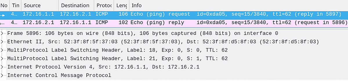
Picture 2: Captured Traffic Between PE1 and P Routers
MPLS forwarding table of PE1 is depicted in Picture 3.
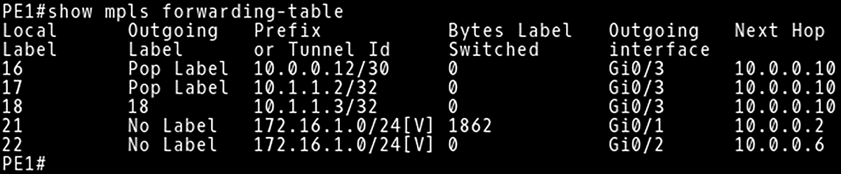
Picture 3: MPLS Forwarding Table of PE1 Router
The label 21 is the inner (VPN) label, added by the PE1 router. It is used to identify the correct next-hop (10.0.0.18) on the PE2 router for Customer A data traffic. The inner label is kept untouched by the P router. Only the PE routers perform either push or pop of the VPN labels. The VPN label for Customer B traffic is 22.
The P router is a transit router that performs pop of LSP labels 18 and 19 (Picture 4). This router takes the forwarding decision solely based on labels. The label 19 is the LSP label pushed on packet by PE2 router when sending traffic to 10.1.1.1.
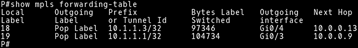
Picture 4: MPLS Forwarding Table of P Router
Picture 5 depicts the captured traffic on the link between P and PE2 routers, while issuing the ping command from PC1A to PC2B. There is only one MPLS header with VPN label 21 because the P router has poped the label 18. Router PE2 removes the inner VPN header 21 and forwards ICMP request as a plain IP packet to CE2A (10.0.0.18).
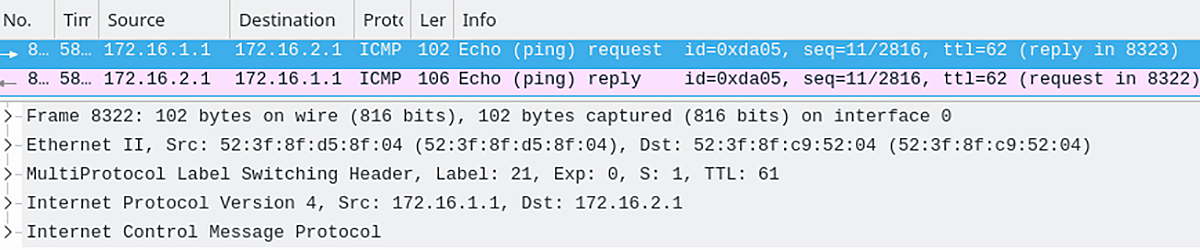
Picture 5: Captured Traffic Between P and PE2 Routers
In the opposite direction, a packet carrying ICMP echo reply message from PC2A to PC1A contains the LSP label in the MPLS header. The VPN label is the same as in echo request (21) because both sides are customer A. Picture 6 depicts MPLS forwarding table of PE2 router.
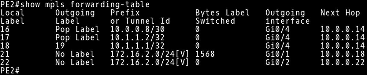
Picture 6: MPLS Forwarding Table of PE2 Router
Picture 7 depicts a forwarding table of the PE2 router for VRF Customer A. It contains two routes learned via BGP. It is the route 172.16.2.0/24 announced by customer router CE2A and the route 172.16.1.0 advertised by the router PE1.
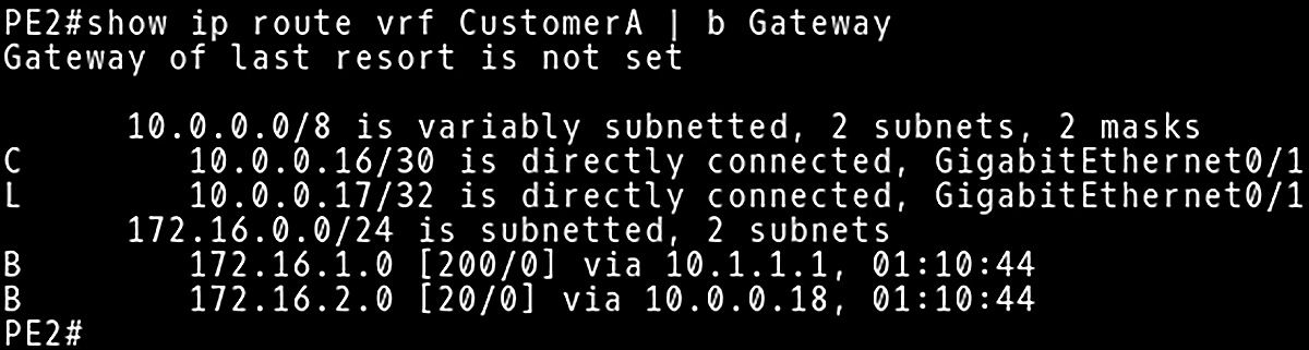
Picture 7: VRF of Customer A on PE2 Router
Inspecting Control Plane
BGP Update message sent from PE1 to PE2 is depicted in Picture 8. Notice, that there is only one MPLS header with LSP label 18, VPN label is missing. It ensures that MP-BGP message is sent via the MPLS network. VPN label is distributed inside the MP-BGP update message along with the unique VPN-IPv4 prefix.
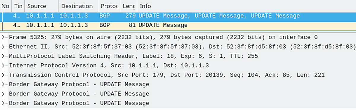
Picture 8: BGP Update Message with LSP label 18
VPN-IPv4 route is a customer’s route that is modified to be unique in order to use the same private IP address for customers. VPN-IPv4 routes consists of the Route Distinguisher (RD) and the prefix. Picture 9 shows the content of the NLRI inside the MP_REACH_NLRI path attribute. It is the prefix 172.16.1.0 with the RD 64501:2 and the label stack (VPN label) 22 (Customer B).
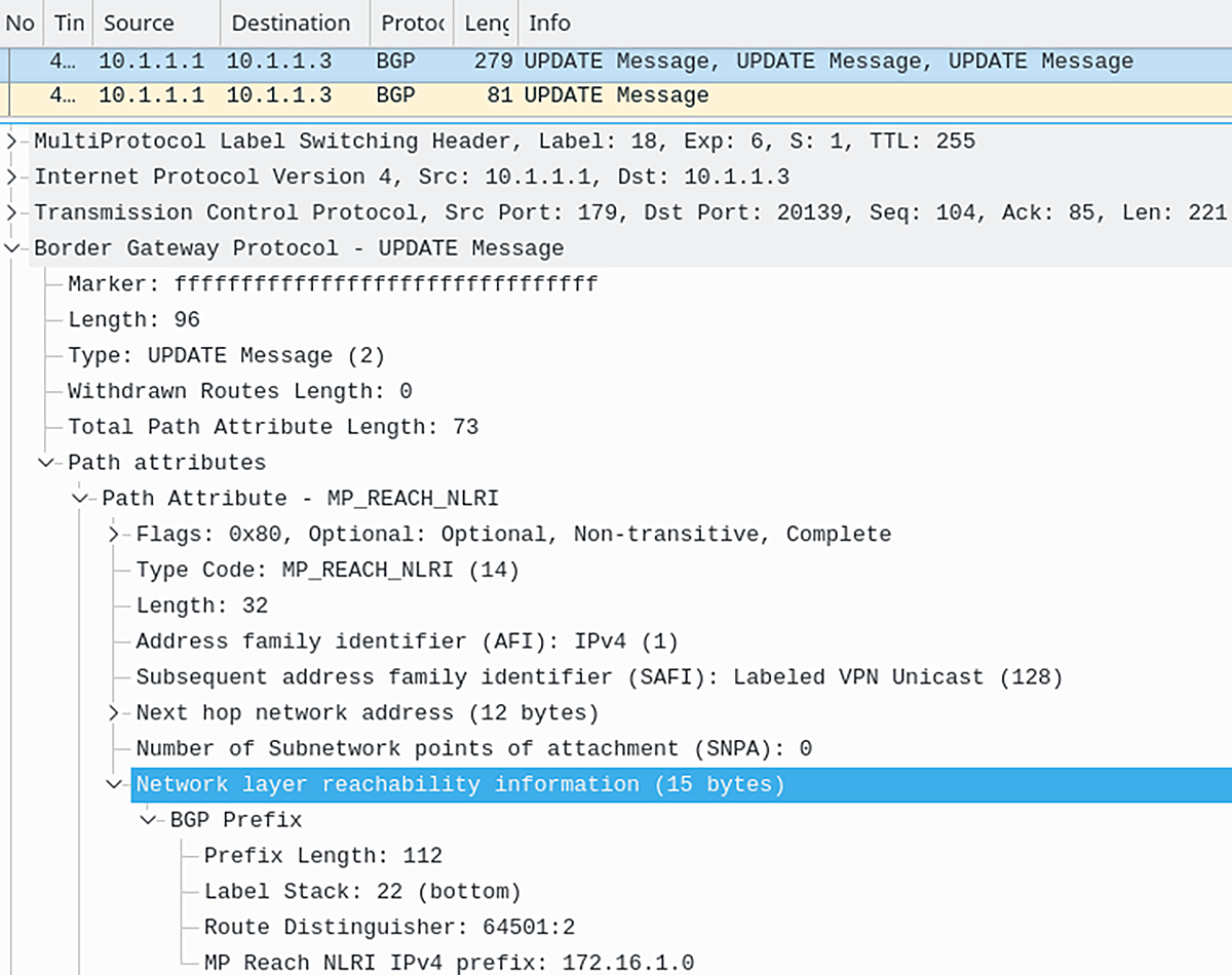
Picture 9: Unique VPN-IPv4 Route
The BGP update message also contains the Path attribute – EXTENDED_COMMUNITIES where the route-target 64501:2 is located. It is shown in Picture 10.
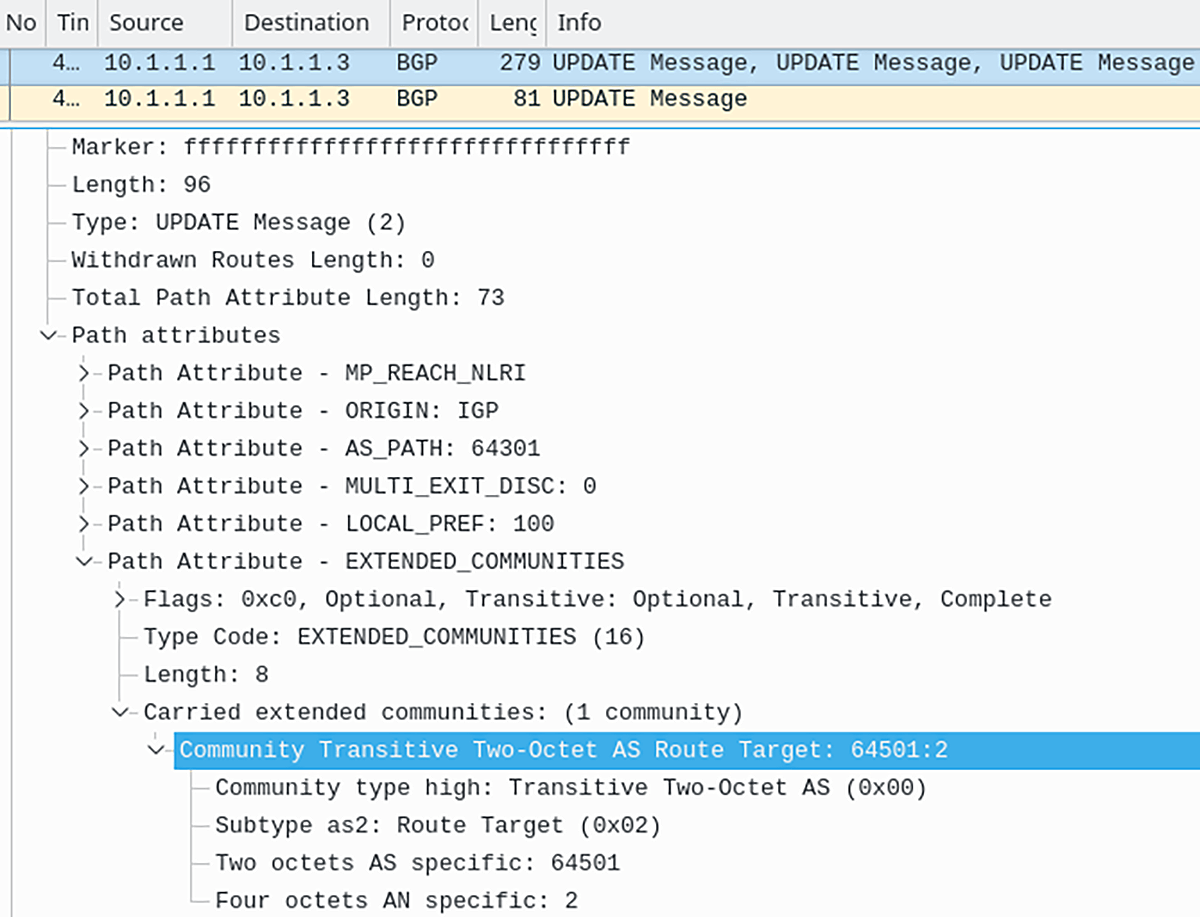
Picture 10: Route Target Inside Extended Community
Conclusion:
We have provided the exact configuration steps that can help our readers create a BGP/MPLS L3 VPNs and grasp the overall concept. If you need to acquire more theoretical knowledge about the BGP/MPLS VPNs concept, read our first blog post.