 In the previous article, we described different DDoS attacks and their impact on network infrastructure. We focused on the BGP flowspec (BGP-FS) based DDoS mitigation techniques, highlighted its importance, and explained the role of scrubbing devices/services, which large providers use as part of their DDoS mitigation toolkit. Next, we outlined the interaction between the BGP-FS controller and clients, as well as the redirection of the corresponding DDoS flow to the scrubber via VRF or IP next hop.
In this article, we will explain the configuration of the FlowSpec controller and client on Cisco devices using the reference topology shown in Figure 1. As part of the test, we will simulate a DDoS ICMP flood against the 190.160.2.1 server. The DDoS will be redirected to the scrubbing appliance via VRF by the provider edge router PE2 based on the FlowSpec rule configured on the controller P.
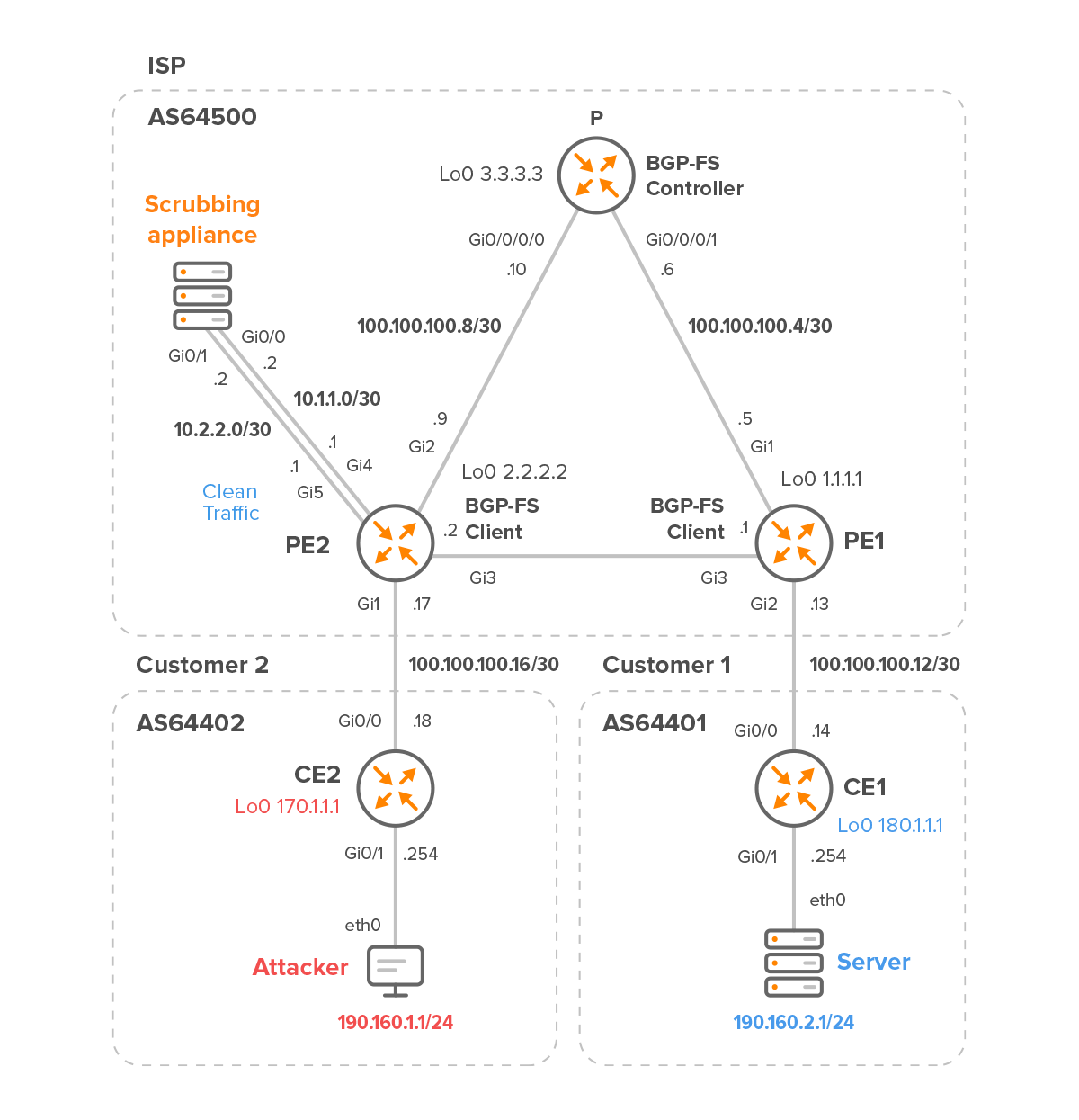
Figure 1 – Internet Service Provider with Customer 2 and 1
The scrubbing appliance is deployed at the network’s edge and connected to PE2.
Routers PE2 and PE1 are Cisco CSR1000v, which we will configure as BGP flowspec clients. To demonstrate the configuration of the BGP flowspec controller on a Cisco IOS-XRv9k, the P router is configured as the controller. The scrubbing appliance is only used to clean “dirty” traffic sent by the edge router PE2 and to forward clean traffic back to PE2.
Table 1 summarizes the software and hardware requirements for the provider’s equipment.
| Location | BGP AS | Hostname | Model | OS | CPU cores | RAM [MB] | Flowspec |
| ISP | 64500 | P | IOS XRv9k | IOS-XRv 6.5.1 | 4 | 8192 | Controller |
| ISP | 64500 | PE1 | CSR1000v | IOS-XE 17.03.04a | 2 | 4096 | Client |
| ISP | 64500 | PE2 | CSR1000v | IOS-XE 17.03.04a | 2 | 4096 | Client |
| ISP | 64500 | Scrubber | – | – | – | – | – |
Table 1 – Internet Service Provider Devices
| NOTE: We will skip the configuration of the customer’s routers altogether and instead focus on the configuration of the provider’s devices. We also do not explain the PE1 router configuration because it is similar to the PE2 router configuration. |
1. Initial Configuration of Provider’s Network
1.1 P router
First, we need to assign IPv4 addresses and enable OSPF on specific interfaces for inter loopback connectivity between ISPs routers:
interface Loopback0
   ipv4 address 3.3.3.3 255.255.255.255

interface GigabitEthernet0/0/0/0
   ipv4 address 100.100.100.10 255.255.255.252

interface GigabitEthernet0/0/0/1
   ipv4 address 100.100.100.6 255.255.255.252

router ospf 1
   router-id 3.3.3.3
   area 0
      interface Loopback0
      interface GigabitEthernet0/0/0/0
      interface GigabitEthernet0/0/0/1
Next, we need to configure basic BGP neighbor establishment:
router bgp 64500
   bgp router-id 3.3.3.3
   address-family ipv4 unicast

   neighbor 1.1.1.1
    remote-as 64500
    update-source Loopback0
    address-family ipv4 unicast
       next-hop-self

   neighbor 2.2.2.2
    remote-as 64500
    update-source Loopback0
    address-family ipv4 unicast
       next-hop-self
1.2 PE2
Again, we need to assign an IPv4 addresses and configure OSPF for loopback connectivity.
interface Loopback0
   ip address 2.2.2.2 255.255.255.255

interface GigabitEthernet1
   ip address 100.100.100.17 255.255.255.252

interface GigabitEthernet2
   ip address 100.100.100.9 255.255.255.252

interface GigabitEthernet3
   ip address 100.100.100.2 255.255.255.252

interface GigabitEthernet5
   ip address 10.2.2.1 255.255.255.252


router ospf 1
   router-id 2.2.2.2
   network 2.2.2.2 0.0.0.0 area 0
   network 100.100.100.0 0.0.0.3 area 0
   network 100.100.100.4 0.0.0.3 area 0
   network 100.100.100.8 0.0.0.3 area 0
   network 190.160.1.0 0.0.0.3 area 0
A static route is needed to access the loopback interface of the Customer 2 edge router.
ip route 170.1.1.1 255.255.255.255 100.100.100.18
We also need to have a BGP IPv4 Unicast neighborship between all neighbors.
router bgp 64500
   bgp router-id 2.2.2.2
   neighbor 1.1.1.1 remote-as 64500
   neighbor 1.1.1.1 update-source Loopback0
   neighbor 3.3.3.3 remote-as 64500
   neighbor 3.3.3.3 update-source Loopback0
   neighbor 170.1.1.1 remote-as 64402
   neighbor 170.1.1.1 ebgp-multihop 2
   neighbor 170.1.1.1 update-source Loopback0

   address-family ipv4
      neighbor 1.1.1.1 activate
      neighbor 1.1.1.1 next-hop-self
      neighbor 3.3.3.3 activate
      neighbor 3.3.3.3 next-hop-self
      neighbor 170.1.1.1 activate
   exit-address-family
2. Redirecting DDoS Traffic to the Scrubbing Appliance via VRF Routing Instance
2.1 BGP Flowspec Controller configuration on Router P
Activate the BGP flowspec address family on the controller and tie it to the neighbor configuration so we can advertise flowspec rules (routes) to PE1 and PE2 clients:
router bgp 64500
  address-family ipv4 flowspec

  neighbor 1.1.1.1
    address-family ipv4 flowspec

  neighbor 2.2.2.2
    address-family ipv4 flowspec
Traffic matched by the attack-fs class will be redirected from a global traffic link to an individual VRF interface on the PE2 and PE1 clients.
The class is matching ICMP packets with a length equal to or less than 80 bytes or equal to or greater than 200 bytes. The source of the matched DDoS traffic is the subnet 190.160.1.0/24, where the attacker is located and the destination of the traffic is the IP address 190.160.2.1. This is the IP address of the server that we will later flood with ICMP requests with a specific packet length.
class-map type traffic match-all attack-fs
   match destination-address ipv4 190.160.2.1 255.255.255.255
   match protocol icmp
   match source-address ipv4 190.160.1.0 255.255.255.0
   match packet length 200-65535 0-80
   end-class-map
The policy-map attack-pbr type pbr binds the class attack-fs to it and defines a desired action for traffic matched by the class attack-fs. The action “redirect nexthop router-target 666:666” will be attached as an extended BGP community matching a route target 666:666 configured under vrf-dirty on both clients.
policy-map type pbr attack-pbr
   class type traffic attack-fs
    redirect nexthop route-target 666:666

   class type traffic class-default

   end-policy-map
The following configuration ties FlowSpec to the PBR policy attack-pbr defined earlier.
flowspec
   address-family ipv4
      service-policy type pbr attack-pbr
And that’s it for the configuration of the BGP-FS controller. We have successfully created a FlowSpec rule (Figure 2):
RP/0/RP0/CPU0:P# show flowspec afi-all
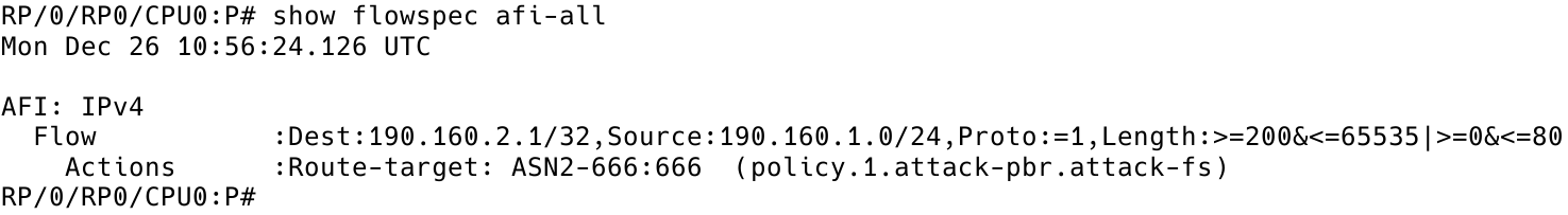
Figure 2 – FlowSpec Rule on Controller
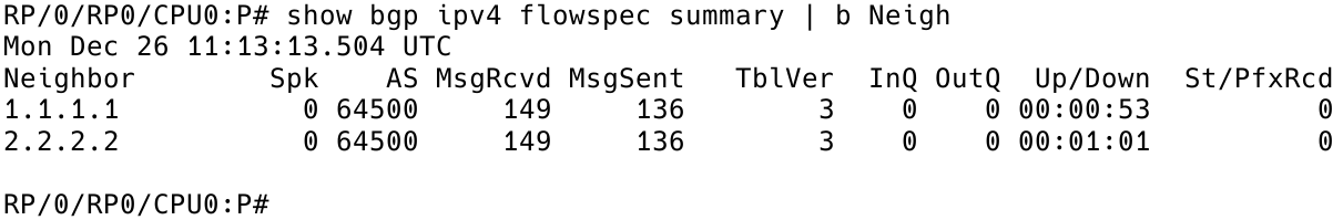
Figure 3 – BGP Flowspec Neighbors on Controller
2.2 BGP Flowspec Client Configuration on Router PE2
The first thing to do is to activate BGP flowspec address family on the client and tie it to the neighbor configuration:
router bgp 64500
  address-family ipv4 flowspec
    neighbor 3.3.3.3 activate
    neighbor 3.3.3.3 send-community both
  exit-address-family
As shown in Figure 4, we have received one prefix from the BGP FlowSpec controller – neighbor 3.3.3.3.
PE2# show bgp ipv4 flowspec summary | begin Neighbor

Figure 4 – Checking BGP FlowSpec Neighbors on Client PE2
vrf definition vrf-dirty
   rd 666:666
   route-target export 666:666
   route-target import 666:666

   address-family ipv4
   exit-address-family
After creating the VRF vrf-dirty, the next step is assigning the VRF to the interface GigabitEthernet 4 which is connected to the scrubbing appliance (Figure 5).
interface GigabitEthernet4
   vrf forwarding vrf-dirty
   ip address 10.1.1.1 255.255.255.252
PE2# show vrf

Figure 5 – VRF Assigned to Interface Gi4
ip route vrf vrf-dirty 0.0.0.0 0.0.0.0 10.1.1.2
PE2# show ip route vrf vrf-dirty | begin Gateway
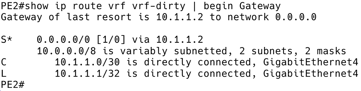
Figure 6 – VRF vrf-dirty Routing Table
flowspec
  local-install interface-all
  address-family ipv4
    local-install interface-all
  vrf vrf-dirty
    address-family ipv4
      local-install interface-all
In order to avoid a routing loop, FlowSpec must be disabled on interface GigabitEthernet5 of PE2. This will allow return traffic from the scrubbing appliance to PE2 to flow eastbound towards PE1 inside GRT.
interface GigabitEthernet5
  ip flowspec disable
2.3 Testing Redirection of DDoS Traffic to a scrubbing appliance via VRF Routing Instance
First of all, let’s check if the flowspec rule is received on the PE2 client (Figure 7).
PE2# show bgp ipv4 flowspec
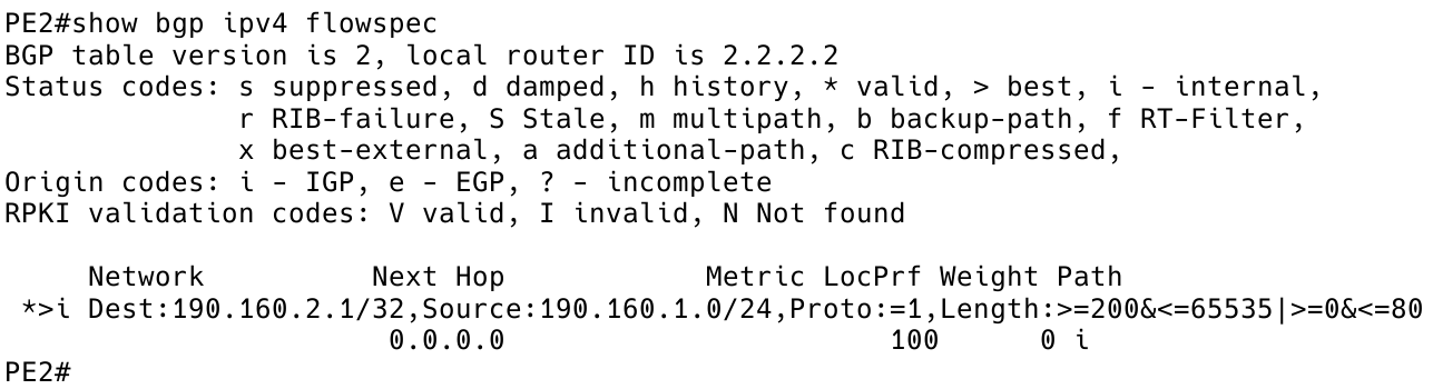
Figure 7 – Flowspec Route (Rule) Received on PE2
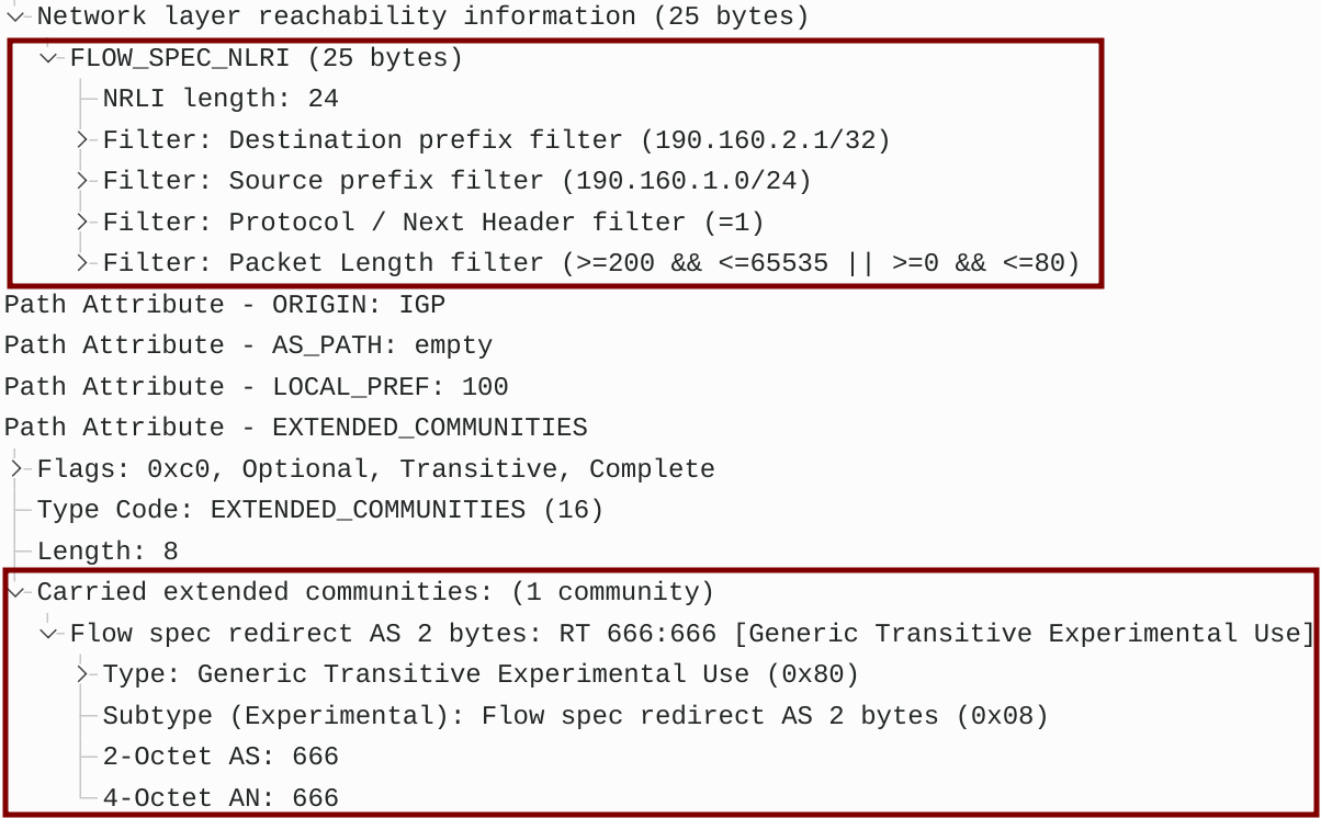
Figure 8 – BGP UPDATE Message Captured Between P and PE2
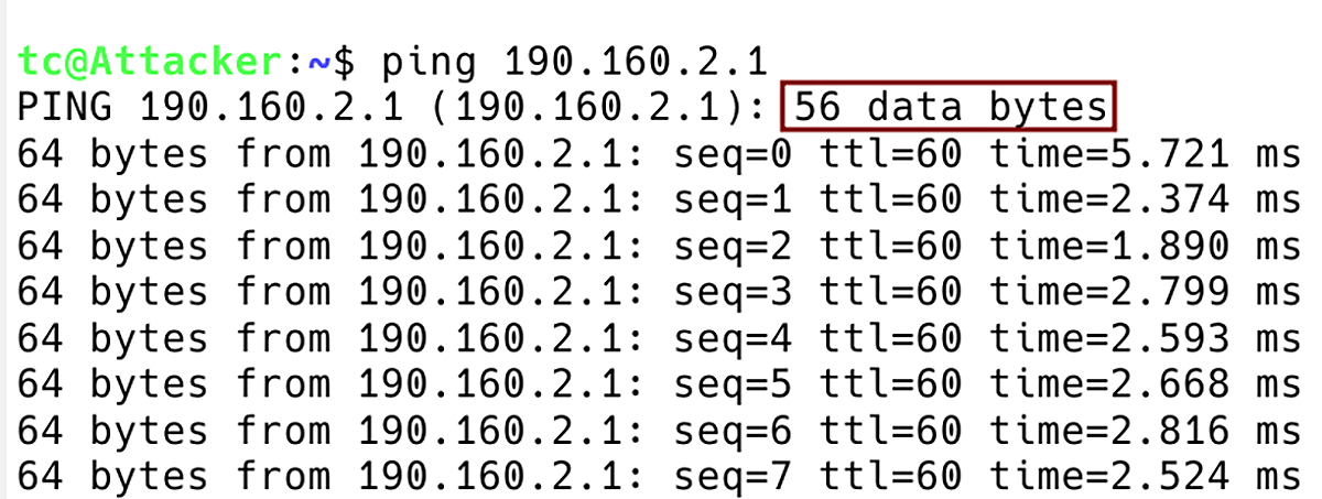
Figure 9 – Flooding Server 190.160.2.1 with Attacker ICMP requests with Default Payload Size of 56 Bytes
PE2# show flowspec vrf all afi-all
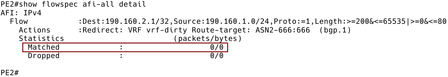
Figure 10 – Zero Packets Matched by Flowspec Rule on Client PE2
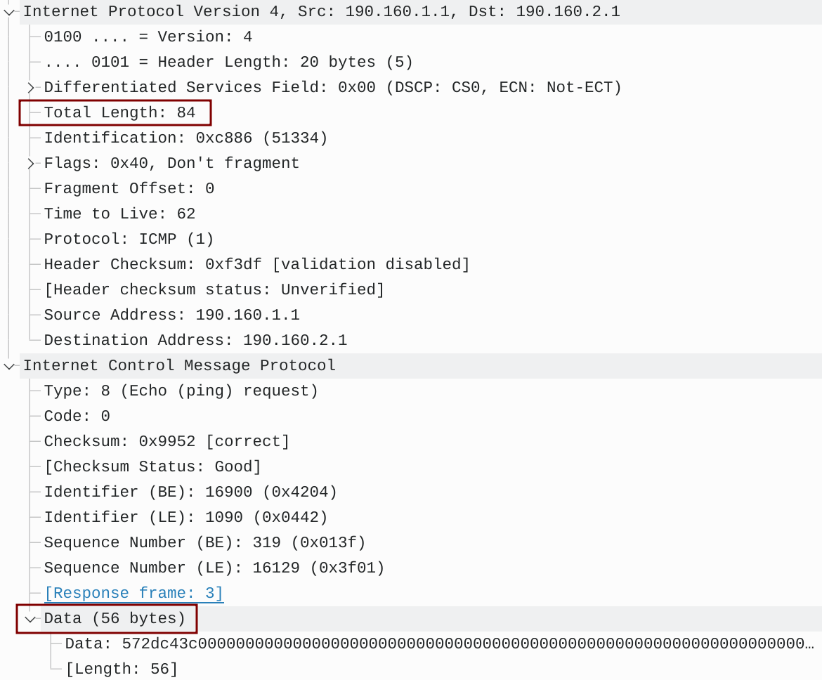
Figure 11 – ICMP Packet Captured on Link Between PE2 and PE1
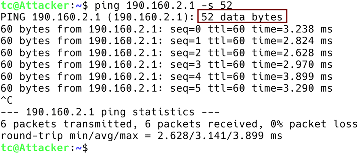
Figure 12 – Flooding Server 190.160.2.1 with ICMP Requests with Data Size of 52 Bytes
PE2# show flowspec vrf all afi-all

Figure 13 – Six Packets Matched by Flowspec Rule on Client PE2
The appliance cleans up traffic and sends it via the Gi0/1 interface back to PE2, which in its turn forwards packets to PE1. ICMP responses from the server are received by PE2 which forwards them to the customer router CE2 under the default VRF (GRT). The Wireshark connected between PE2 and the appliance complains about the missing ICMP responses.

Figure 14 – ICMP Request Captured Between PE2 and the scrubbing appliance
Conclusion
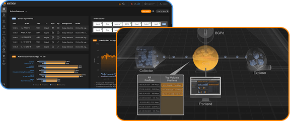
We hope the above information will help out those network administrators looking to protect their networks against DDoS attacks by redirecting malicious traffic to scrubbing appliances via VRF. Should you want to automate DDoS detection and mitigation actions within your network, consider looking at the latest Noction Intelligent Routing Platform version, featuring the FlowSpec Redirect and BGP redirect threat mitigation mechanisms.