 Large-scale data centers (DCs) connect hundreds of thousands or even more servers, having millions of users. Generally, every DC runs two kinds of applications. Applications serving web pages, generating onward network traffic that leaves the DC. Traffic is sent as a query from users to servers and then back, as a response from servers to the users. It is called north-south or server-to-user traffic. Other type of applications generates traffic that mostly stays within the DC. Traffic is called east-west or server-to-server traffic. According to the Microsoft researcher, David A. Maltz, it often amounts to 80% of all DC traffic. The source of server-to-server traffic might be virtual machine migrations, web index computation, extensive data replication between clusters or mailbox moving. As a result of this, traffic is extensively exchanged between servers inside a DC. According to the statistics of the large-scale DC operators, east-west traffic continues to grow exponentially. Nathan Farrington, the former data center network engineer at Facebook claims that a particular HTTP request (north-south traffic) requires 88 cache lookups (648 KB), 35 database lookups (25.6 KB), and 392 backend remote procedure calls (257 KB). If the user’s original HTTP request is 1 KB, then this represents a 930x increase in internal data center traffic.
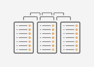
The old DCs were designed mostly for the north-south traffic flow, using the hierarchical network model (Picture 1), also called the tree-based design. This network topology is not very suitable for massive east-west traffic. Let’s say that server1 wants to communicate with server8. In this case, traffic takes a path through one of the Core switches as the Core layer acts as trunk for the lower layers. However, when server1 sends packets to server4, packets do not flow across the Core layer. Obviously, the path and latency differ in this case. When the DC grows, not only another distribution switch is added to Tier2 but also the big and expensive Core switches must be upgraded in order to cover increased bandwidth requirements of the lower tier. The change in the lower Tier2 enforces the change in upper layer – Tier1. The tree-based design limits the DC to be scalable horizontally because existing network elements are affected by newly added network elements, which is not cost-effective. It is mainly inconsistent latency of north-south traffic between servers requiring fast east-west traffic flow, along with limitation of tree-based topology to scale horizontally, that prevent using tree-based design in modern large-scale DCs.
Picture 1: Hierarchical or the Tree-based DC Design.
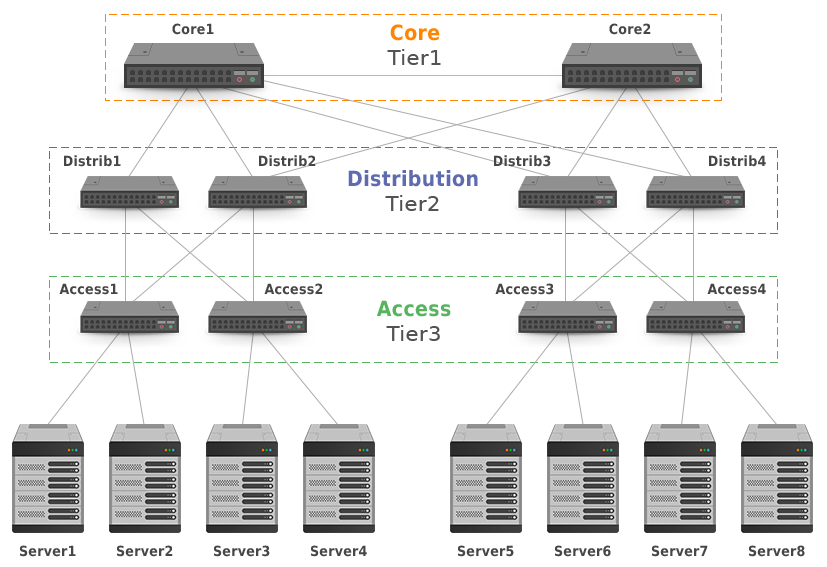
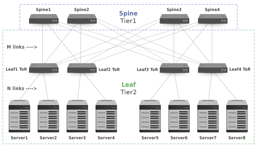
The Clos architecture (Picture 2) provides a significant amount of bandwidth for the server-to-server traffic and consistent latency, as the number of hops between servers is always the same. In contrast of the tree-based model, the Core layer (Tier1) or Spine consists of the multiple cheap Layer3 switches. The Access layer (Tier2) or Leaf also contains layer 3 switches (leaves) that connect servers to the DC network. In 3-stage Leaf and Spine model (Picture 2), leaf switches are also Top-of-Rack (ToR) switches. In a 5-stage model used in very large DCs, there are three tiers, where ToR switches represent a separate Tier3.
| Note: Clos networks are named after Charles Clos, known for the multi-stage circuit telephone network design. |
The leaf and spine switches are connected with point-to-point Layer 3 links. Every leaf switch connects to every spine switch. If the M>= N where M is the number of the links between spine and leaf switches, and N is the number of the links between leaf switches and servers, topology is fully non-blocking. The Clos network does not represent a bottleneck for server-to-server traffic as there is always an unused input on an ingress switch that can be connected to an unused output on an egress switch. Moreover, the topology is horizontally scaled by adding more links and unified spine or leaf switches without upgrading existing network devices.
| Note: Input and output stages are merged for the switch in folded Clos topology. |
In Spine and Leaf topologies it is desirable to push routing down to ToR switches in order to avoid the L2 domains and problems connected with them. Those are typically broadcast and unicast storms that negatively impact network performance and availability. The other key benefit of the L3 design is that the Equal-cost multi-path routing (ECMP) can be employed. Using ECMP, traffic destined to the same prefix is load-balanced over multiple L3 uplinks between spine and leaf switches, so the spine switches are utilized equally.
Picture 2: 3-Stage Clos Network Topology (Two Tiers).
Now the question is what routing protocol is the most appropriate for the L3 large-scale DCs with Clos topology. IGP protocols such as OSPF or IS-IS might be used as they are open-standard, thus all network vendors support them. However, they do not fulfill the requirement of the single routing protocol used everywhere in DC as there is always BGP to connect to the edge of a DC. So, can BGP be used in a DC as well? In terms of the routing protocol scalability, BGP beats any IGP. BGP carries around 700 thousand public IP prefixes, so it can easily accommodate all the DC routes. BGP is also known for excellent prefix filtering. It can match prefixes inward and outbound. It is also good at tagging network traffic with extended communities. Traffic engineering is accomplished by using BGP attributes such as WEIGHT (Cisco only), LOCAL_PREF, MED, so the traffic can be directed to a particular spine switch if needed.
Let’s discuss BGP design on the 5-stage Clos topology with four clusters (Picture 3). The cluster is a single operational or maintenance unit consisting of Tier2 and Tier3 switches along with connected servers. The topology can be scaled horizontally at every layer. BGP is running on all switches in a topology. Every lower-tier device in the topology uses all of its directly attached upper-tier devices to load-share server traffic destined to the same IP prefix. A single private ASN 64512 is configured on all spine switches. The leaf switches in a cluster and each ToR switch have assigned their unique private ASNs. Private AS numbers are assigned from the range 64512-65534, consisting of 1023 numbers in total. To prevent consumption of private ASNs, the ToR switches can re-use the ASNs across the clusters. In this case, the allowas-in feature must be configured on Tier3 switches. It keeps BGP loop prevention mechanism on ToR switches from suppressing routes, accepting the same ASN in received advertisements. Another approach is to use 4-octet AS number, supporting 94 967 295 private ASNs. However, in this case, all the switches in the topology must support 4-octet ASN. At the edge of the DC, private AS numbers are stripped from AS_PATH attribute. A static default route is injected into the BGP for out of DC connectivity.
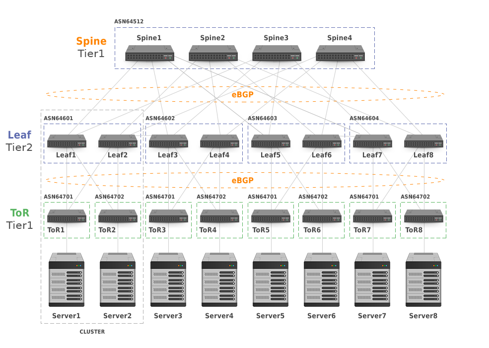
Picture 3: 5-Stage Clos Network Topology with Clusters
Subnets configured on Point-to-point (P2P) links between the switches use the mask /31 in order to save IP addresses. It is not necessary to advertise the P2P prefixes, as the eBGP changes a next-hop address on every switch and the server subnets are reachable anyway. If connectivity to the P2P subnets is needed e.g. for management or troubleshooting purpose (ssh, ping, traceroute), summarization of the P2P prefixes on all tiers is more than welcome.
BGP drawbacks that might prevent the protocol from being used in a large-scale data centers can be effectively minimized. For instance, bigger configuration overhead (AS numbers and neighbors definition) may be reduced by the automated generation of the configuration files. Once standardized and implemented, IETF BGP neighbor auto-discovery drafts can remove a need of static BGP peers definition thus effectively reducing configuration overhead. Another perceived disadvantage of BGP – the slower routing convergence is minimized on point-to-point links where the most BGP implementations shutdown BGP sessions in case of a link failure. Convergence is then a matter of a few seconds. Also, Bidirectional Forwarding Detection (BFD) might be employed and fall-over bfd feature configured for BGP for faster dead peer detection.
The operational experiences of the large-scale DC operators prove that BGP is well suited for use in their data centers. The implementation of BGP in data centers can allow a small group of people to effectively support a very large network due to operational simplicity and network stability it offers.