
Fast Reroute (FRR) is a technique used in MPLS TE to minimize the impact of link or node failures on traffic. When a failure occurs, FRR allows traffic to be quickly rerouted onto a backup path without waiting for the network to converge on a new path. Therefore, MP is a critical component of FRR because it is where the backup and primary paths converge.
When a failure occurs on the primary path, the backup path is activated, and traffic is rerouted to the MP. At the Merge Point, the traffic from the primary and backup paths are merged and forwarded toward the destination. The MP ensures that there is no packet loss or duplication when the traffic is merged from both paths.
To illustrate this concept, consider the topology depicted in Figure 1. In the topology, the red path represents the primary LSP (Label Switched Path) and carries the traffic. The green path, on the other hand, represents the backup LSP and is used only in case of failure. If a link fails, such as between Router P1 and P3, the traffic cannot be carried between Router PE1 and PE2 through the red LSP.
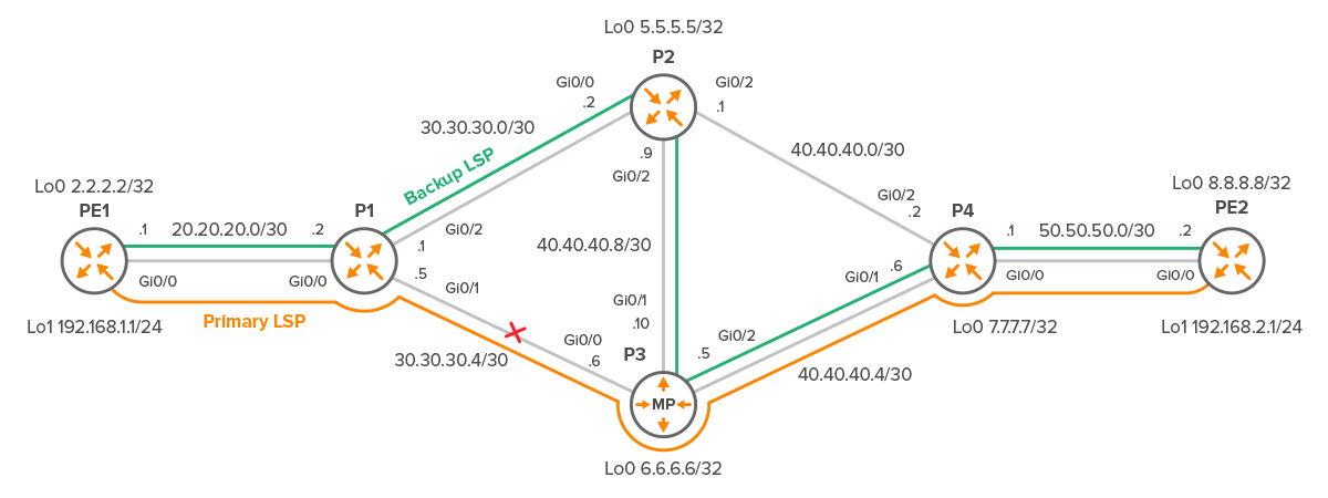
Figure 1 – MPLS TE with Primary and Backup Label Switched Paths
The next part will guide you through the process of creating a network topology similar to the one shown in Figure 1 and configuring an MPLS TE tunnel between routers PE1 and PE2. By doing so, you will gain a better understanding of how the backup Label Switched Path (LSP) connects to the primary LSP at the Merge Point.
Additionally, we will explore the configuration of Fast Reroute (FRR) link protection and its role in ensuring rapid traffic restoration in the event of a link or node failure. This practical guide will help you understand the concepts of MPLS TE, FRR, and Merge Point and how they work together to enhance network resiliency.
1. MPLS TE Configuration
MPLS tunnels are unidirectional, which means we need one tunnel in each direction to send traffic. In the case of tunnel12 from PE1 to PE2, the headend or start of the tunnel is Router PE1 with 20.20.20.1 configured, while the tailend is 50.50.50.2 configured on PE2. Similarly, for tunnel 21 from PE2 to PE1, the headend is Router PE2, and the tailend is PE1.
To exchange link and loopback subnets, OSPF is enabled on all routers.
To reserve and exchange labels, it is necessary to enable RSVP on all interfaces except loopback interfaces.
1.1 PE1 Configuration
mpls traffic-eng tunnels

interface Loopback0
 ip address 2.2.2.2 255.255.255.255
Note that the Loopback1 IP address 192.168.1.1 is used for testing tunnel connectivity between PE1 and PE2 routers and is not related to the MPLS TE configuration.
interface Loopback1
 ip address 192.168.1.1 255.255.255.0
Enable MPLS TE and RSVP on all Gigabit-Ethernet interfaces with a bandwidth reservation of 512 kbps.
interface GigabitEthernet0/0
 ip address 20.20.20.1 255.255.255.252
 mpls traffic-eng tunnels
 ip rsvp bandwidth 1024 1024
Configure OSPF routing protocol for MPLS TE and OSPF area to run TE.
router ospf 1
 mpls traffic-eng router-id Loopback0
 mpls traffic-eng area 0
 router-id 2.2.2.2
 network 2.2.2.2 0.0.0.0 area 0
 network 20.20.20.0 0.0.0.3 area 0
Define explicit path for PE1-PE2 tunnel: PE1→ P1 → P3→ P4 and PE2.
ip explicit-path name PE1-PE2 enable
 next-address 20.20.20.2
 next-address 30.30.30.6
 next-address 40.40.40.6
 next-address 50.50.50.2
Create a tunnel interface, and define the MPLS-TE tunnel encapsulation method, tunnel destination, bandwidth, priority, and other relevant parameters.
interface Tunnel12
 ip unnumbered Loopback0
 tunnel mode mpls traffic-eng
 tunnel destination 8.8.8.8
 tunnel mpls traffic-eng priority 2 2
 tunnel mpls traffic-eng bandwidth 512
 tunnel mpls traffic-eng path-option 1 explicit name PE1-PE2
 tunnel mpls traffic-eng fast-reroute
 no routing dynamic
We also need to route traffic to the 192.168.2.1 loopback interface of PE2 through the tunnel12 interface.
ip route 192.168.2.0 255.255.255.0 Tunnel12
1.2 P1, P2, P3 and P4 Configuration
We will only showcase the configuration of the P1 transit router, as the configuration of the other routers is similar and, therefore, not necessary to present.
mpls traffic-eng tunnels

interface Loopback0
 ip address 4.4.4.4 255.255.255.255


interface GigabitEthernet0/0
 ip address 20.20.20.2 255.255.255.252
 mpls traffic-eng tunnels
 ip rsvp bandwidth 1024 1024

interface GigabitEthernet0/1
 ip address 30.30.30.5 255.255.255.252
 mpls traffic-eng tunnels
 ip rsvp bandwidth 1024 1024

interface GigabitEthernet0/2
 ip address 30.30.30.1 255.255.255.252
 mpls traffic-eng tunnels
 ip rsvp bandwidth 1024 1024

router ospf 1
 mpls traffic-eng router-id Loopback0
 mpls traffic-eng area 0
 router-id 4.4.4.4
 network 0.0.0.0 255.255.255.255 area 0
1.3 PE2 Configuration
mpls traffic-eng tunnels

interface Loopback0
 ip address 8.8.8.8 255.255.255.255

interface Loopback1
 ip address 192.168.2.1 255.255.255.0

interface GigabitEthernet0/0
 ip address 50.50.50.2 255.255.255.252
 mpls traffic-eng tunnels
 ip rsvp bandwidth 1024 1024

router ospf 1
 mpls traffic-eng router-id Loopback0
 mpls traffic-eng area 0
 router-id 8.8.8.8
 network 8.8.8.8 0.0.0.0 area 0
 network 50.50.50.0 0.0.0.3 area 0

ip explicit-path name PE2-PE1 enable
 next-address 50.50.50.1
 next-address 40.40.40.1
 next-address 30.30.30.1
 next-address 20.20.20.1

interface Tunnel21
 ip unnumbered Loopback0
 tunnel mode mpls traffic-eng
 tunnel destination 2.2.2.2
 tunnel mpls traffic-eng priority 2 2
 tunnel mpls traffic-eng bandwidth 512
 tunnel mpls traffic-eng path-option 1 explicit name PE2-PE1
 tunnel mpls traffic-eng fast-reroute
 no routing dynamic

ip route 192.168.1.0 255.255.255.0 Tunnel21
1.4 Verification
To begin, we verify the operational status of tunnel 12 on router PE1, as shown in Figure 2.
PE1# show mpls traffic-eng tunnels
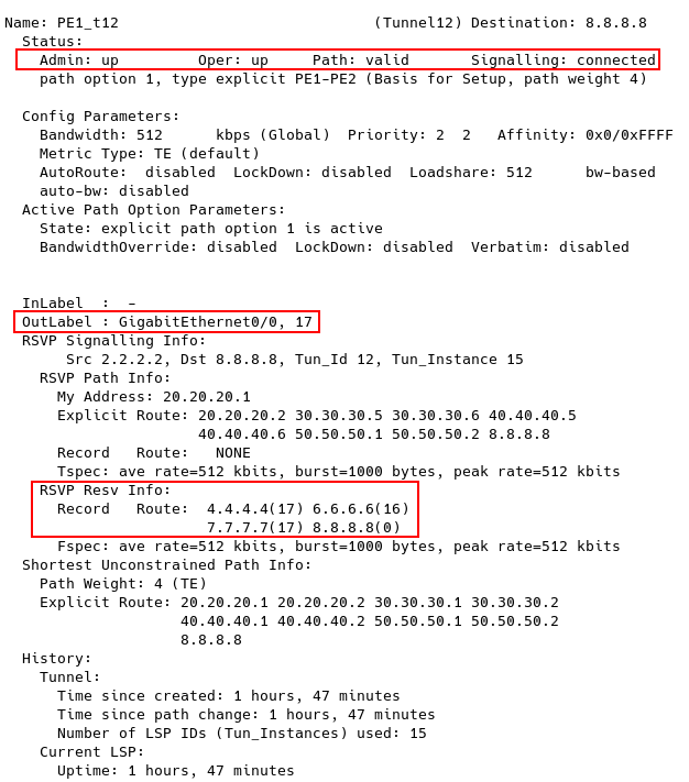
Figure 2 – Checking MPLS TE Tunnels on PE1 – Tunnel12

Figure 3 – P1 MPLS Forwarding Table
PE2# show mpls traffic-eng tunnels
We can see in Figure 4 that the MPLS TE Tunnel31 on PE2 is also up and running. Any traffic destined for PE2 is placed into the tunnel and takes a path that passes through P4, P2, P1, and finally reaches PE1.
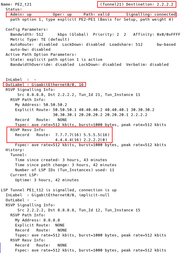
Figure 4 – Checking MPLS TE Tunnels on PE2 – Tunnel 21

Figure 5 – Checking Connectivity from PE1 to PE2
2. MPLS TE Fast Reroute Link Protection
We have set up a primary MPLS TE tunnel between PE1 and PE2, with a path through P1, P3, and P4. However, if the link between P1 and P3 fails, we’ll lose connectivity to the tunnel endpoint, since the path is explicitly configured on PE1.
MPLS TE Fast Reroute (FRR) is a mechanism that provides fast protection against link and node failures in the network, ensuring that traffic is rerouted quickly and efficiently to avoid data loss. By default, MPLS TE calculates a new best path when there is a failure in the primary tunnel, but this process can be too slow for delay-sensitive applications such as VOIP. With MPLS TE fast reroute, traffic is forwarded down a backup tunnel when there is a failure in the primary tunnel, allowing a faster recovery time of less than 50 ms.
To bypass the link between P1 and P3, we will configure a backup NHOP (Next Hop) tunnel from P1 through P2, terminating at P3. The headend router of the backup tunnel is node P1, and the tailend router is the merge point (MP) – node P3. If the link between P1 and P3 fails, we’ll still have a path to the TE tunnel endpoint, avoiding data loss.
In the following parts, we will enable link protection backup tunnel 100 on both P1 and P3 and associate the interface Gi0/1 with the backup tunnel on P1. When the interface Gi0/1 goes down, the backup tunnel is activated.
2.1 Backup Tunnel Configuration on P1
Assuming that the primary tunnel from PE1 to P2 is already configured and operational, we start configuring the backup tunnel on P1.
interface Tunnel100
 description "Link Protection Tunnel"
 ip unnumbered Loopback0
 tunnel mode mpls traffic-eng
 tunnel destination 6.6.6.6
 tunnel mpls traffic-eng path-option 1 explicit name P1-P3
 no routing dynamic

interface GigabitEthernet0/1
 ip address 30.30.30.5 255.255.255.252
 mpls traffic-eng tunnels
 mpls traffic-eng backup-path Tunnel100
 ip rsvp bandwidth 1024 1024

ip explicit-path name P1-P3 enable
 next-address 30.30.30.2
 next-address 40.40.40.10
2.2 Backup Tunnel Configuration on P3
interface Tunnel100
 description "Protection tunnel"
 ip unnumbered Loopback0
 tunnel mode mpls traffic-eng
 tunnel destination 4.4.4.4
 tunnel mpls traffic-eng path-option 1 explicit name P3-P1
 no routing dynamic

ip explicit-path name P3-P1 enable
 next-address 40.40.40.9
 next-address 30.30.30.1
2.3 PE1 Configuration
After configuring a backup tunnel on both P1 and P3 and associating it with the gi0/1 on both P1, one more step is required to ensure its proper functioning. Specifically, fast-reroute must be enabled on the TE tunnel configured on PE1 so that tunnel12 is fast-rerouted.
interface Tunnel12
 tunnel mpls traffic-eng fast-reroute
2.4 Verification
Firstly, we will check the status of the backup tunnel on P1 router (Figure 6):

Figure 6 – Checking MPLS TE FRR Database Before Link Failure Between P1 and P3
Therefore, packets sent from P1 to P2 via the backup path from the Gi0/2 interface when the backup tunnel is activated will have two labels. The inner label expected by P3 is 16, and the outer label inserted by P1 is 18 (Figure 7).
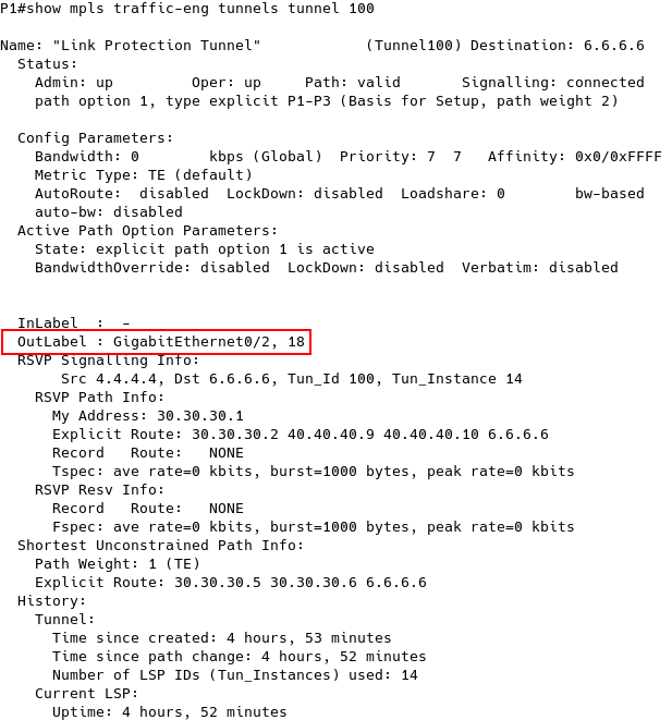
Figure 7 – Checking Backup Tunnel 100 on P1
3. Testing MPLS TE Fast Reroute Link Protection
We now disable the Gi0/1 interface on P1 to simulate a link failure between P1 and P3:
P1(config)# int gi0/1
P1(config-if)# sh
The backup path via P2 is now activated, and the status changes from ready to active (Figure 8).

Figure 8 – Checking MPLS TE FRR Database After Link Failure Between P1 and P3
PE1# traceroute 192.168.2.1
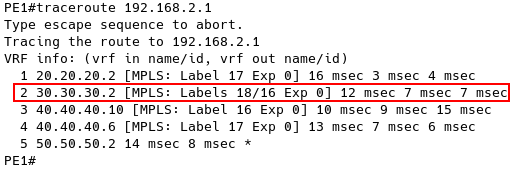
Figure 9 – Checking Connectivity between PE1 and PE2 After Link Failure on P1

Figure 10 – Capture Packets between PE1 and PE2 After Link Failure on P1
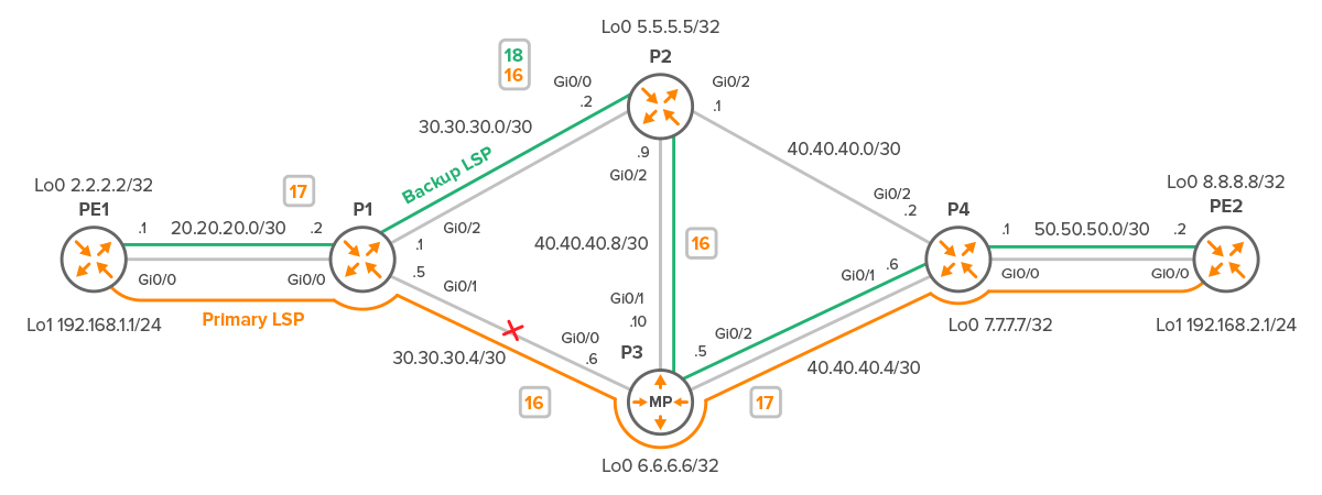
Figure 11 – MPLS Label Assignment on Backup Path from PE to PE2

Figure 12 – Popping Label 18 on P2
Conclusion:
MPLS Traffic Engineering (TE) provides a way to optimize network traffic and ensure efficient use of network resources.
Using a Merge Point (MP) and Fast Reroute (FRR) techniques in MPLS TE enables network operators to minimize the impact of link and node failures on traffic and ensure faster restoration of services.
The MP is a critical component of FRR, ensuring that traffic from the primary and backup paths is seamlessly merged without any packet loss or duplication.
Network operators need to understand the concept of MP, FRR, and MPLS TE to deploy these technologies effectively and enhance the overall resiliency of their networks. By leveraging these techniques, network operators can ensure that their networks are always available and provide high-quality services to their customers.


