 Quality of Service (QoS) refers to a collection of technologies that networking devices use to apply different treatment to packets as they pass through the devices. There are several QoS techniques for this, such as classification and marking, shaping and policing, queuing and congestion avoidance.
1. Packet Classification
Classification is the process of matching fields in the headers in order to identify packets that take a particular QoS action such as queuing, policing, shaping etc. The fields such as protocol type, source or destination IP address can be matched in an IP header. There is also a source or a destination port in a TCP header that is matchable for QoS classification. An extended IP access list with a permit action can be used to match any of these fields.
| Note: QoS Policy Propagation via BGP (QPPB) allows to classify packets based on access lists, BGP community lists, and BGP AS path. We will discuss it later. |
2. Packet Marking
Marking is the process of changing the IP packet headers so that such packets get marked and given a preferred treatment. Packets can be marked with either the IP Precedence or a DSCP value.
| Note: Classification and marking of packets is usually done on the edge devices. All network devices along the path that support Diffserv use the DSCP value (codepoint) in the IP header to select a per-hop behavior (PHB) for the packet and to provide the appropriate QoS treatment. We will discuss DSCP later. |
RFC 791 defines the legacy way of marking the IP header of packets with IP precedence.
2.1 Packet Marking with IP Precedence
There is an 8 bits value field inside of the IP header dedicated for QoS. The RFC 791 defines it as the Type of Service (TOS) byte (Picture 1). The bits T2, T1, T0 set delay, throughput and reliability, accordingly. For instance, the bit T2 = 0 means normal delay, while T2 =1 means low delay. The bits T2, T1 and T0 however, have not been used in practice, only the precedence bits were used. The bits CU1 and CU0 refer to Currently Unused and are reserved for the future use.
| P2 | P1 | P0 | T2 | T1 | T0 | CU1 | CU0 |
Picture 1: Bits inside the ToS Byte
The bits P2, P1 and P0 sets IP precedence to the packet. There are a total of 8 values with the higher value representing the higher preference. Packets with the lower precedence will be dropped by a router first in case of congestion. For instance, the lowest precedence of value 0 is set by a combination of bits 000 (Routine). The highest preference of value 7 is set by a combination of bits 111 (Network control).
2.2 Packet Marking with DSCP
Even though the IP precedence works well, it offers only 8 precedence values. RFC 2474 solves this drawback and replaces the TOS field inside of an IP header with a Differentiated Services (DS) field. The first 6 bits of a DS field are used to set the Differentiated Services Code Point (DSCP) values aka codepoints. The 6-bit DSCP field inside of a DS field gives us 64 DSCP values that are used for marking packets. (Picture 2).
| DS5 | DS4 | DS3 | DS2 | DS1 | DS0 | CU | CU |
Picture 2: Bits inside DS Byte
The two-bit Currently Unused (CU) field is reserved.
| Note: Differentiated services (DiffServ) is a computer networking architecture that specifies a simple and scalable mechanism for classifying and managing network traffic and providing quality of service (QoS) on modern IP networks [1]. |
There are three sets of DSCP values used in DiffServ.
2.2.1 Expedited Forwarding (EF)
The Expedited Forwarding (EF) DSCP value is a single decimal value – 46 (binary pattern 101110) used for marking packets that need low delay, low jitter and low loss. By default, Cisco IP phones mark voice payload (RTP) with the EF value of 46 and the signalization packets (SIP or SCCP) with CS3.
2.2.2 Class Selector (CS)
The DSCP Class Selector (CS) is created for backward compatibility with the legacy IP precedence QoS model that is using a 3-bit IP precedence field. The CS set contains 8 DSCP values, each matching one IP precedence value. For instance, CS0 is matching the IP precedence 0 and so on. As DSCP values are 6-bits, the first three bits in CS are matching the 3-bit IP precedence while the other three CS bits are set to 0. Table 1 shows matching IP precedence and Class selector values.
| IP Precedence (IPP) | Class Selector (CS) | ||||
| Name | Decimal | Binary | Name | Decimal | Binary |
| Routine | 0 | 000 | CS0 | 0 | 000 000 |
| Priority | 1 | 001 | CS1 | 8 | 001 000 |
| Immediate | 2 | 010 | CS2 | 16 | 010 000 |
| Flash | 3 | 011 | CS3 | 24 | 011 000 |
| Flash Override | 4 | 100 | CS4 | 32 | 100 000 |
| Critic/Critical | 5 | 101 | CS5 | 40 | 101 000 |
| Internetwork Control | 6 | 110 | CS6 | 48 | 110 000 |
| Network Control | 7 | 111 | CS7 | 56 | 111 000 |
Table 1: Matching Between CS and IPP
2.2.3 Assured Forwarding (AF)
Assured Forwarding (AF) is a set of 12 DSCP values that provide priority values to different data applications. RFC 2597 defines four AF classes and three levels of drop preference (probability) in each class. The AF name is presented in the Afxy format, where x refers to the class (1 through 4) and y refers to the drop probability (1- low, 2 – medium, 3 – high).
The packets marked with codepoints AF11, AF12 and AF12 would go into one queue of a router while packets marked with AF21, AF22 and AF33 would go to another.
Inside the queue 1, packets marked with AF13 would be dropped before the packets with AF11, since they are marked with a higher drop probability.
| Note: AF13 is a decimal 001 110. The first three bits 001 represent an AF class indicator (decimal 1), the next two bits 11 are the drop preference within the class (decimal 3). The last bit of the six bit field is always zero in an AF model. If the sixth bit is set to 1, the DSCP is a user defined value. |
3. QoS Policy Propagation via BGP (QPPB)
QPPB allows marking of packets based on an IP precedence or QoS group value (internal to the router) associated with a Border Gateway Protocol (BGP) route. A local router in a given AS influences the IP precedence of traffic (or QoS group) that is sent to the router from a remote AS based on the BGP attributes such as AS path or BGP communities. The QoS Policy is therefore implicitly propagated to the remote AS via BGP. Once a packet is classified, QoS features such as Committed Access Rate (CAR) and Weighted Random Early Detection (WRED) can be used to specify and enforce policies.
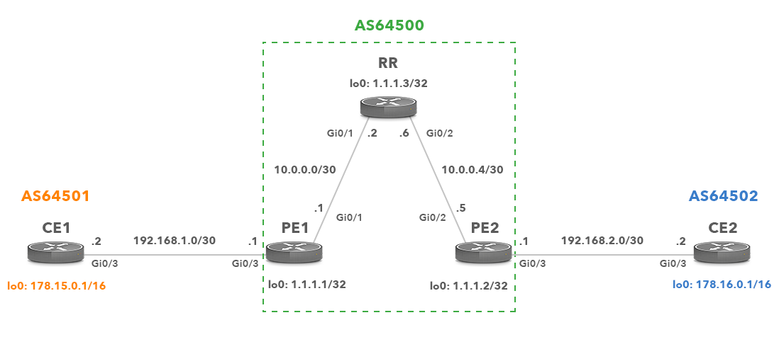
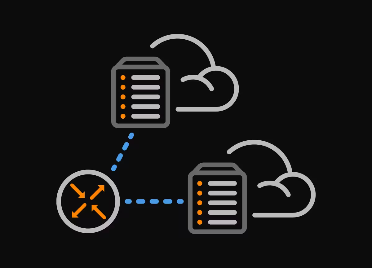
Picture 3: Network Topology
Let’s look at the following scenario. A customer (AS64501) has an agreement with the ISP (AS64500) regarding the 172.15.0.0/16 prefix. Traffic to and from the 172.15.0.0/16 prefix between AS64501 and AS64502 is treated preferentially within AS64500.
3.1 Initial Configuration
CE1
interface Loopback0
 ip address 178.15.0.1 255.255.0.0

interface GigabitEthernet0/3
 ip address 192.168.1.2 255.255.255.252

router bgp 64501
 network 178.15.0.0
 neighbor 192.168.1.1 remote-as 64500
PE1
interface Loopback0
 ip address 1.1.1.1 255.255.255.255

interface GigabitEthernet0/1
 ip address 10.0.0.1 255.255.255.252

interface GigabitEthernet0/3
 ip address 192.168.1.1 255.255.255.252
AS64500 runs OSPF as IGP for internal reachability.
router ospf 1
 network 1.1.1.1 0.0.0.0 area 0
 network 10.0.0.0 0.0.0.3 area 0

router bgp 64500
 network 10.0.0.0 mask 255.255.255.0
 neighbor 1.1.1.3 remote-as 64500
 neighbor 1.1.1.3 update-source Loopback0
 neighbor 1.1.1.3 next-hop-self
 neighbor 192.168.1.2 remote-as 64501
Static null route is needed to advertise prefix 10.0.0.0/24 via BGP.
ip route 10.0.0.0 255.255.255.0 Null0
RR
interface Loopback0
 ip address 1.1.1.3 255.255.255.255

interface GigabitEthernet0/1
 ip address 10.0.0.2 255.255.255.252

interface GigabitEthernet0/2
 ip address 10.0.0.6 255.255.255.252

router ospf 1
 network 1.1.1.3 0.0.0.0 area 0
 network 10.0.0.0 0.0.0.3 area 0
 network 10.0.0.4 0.0.0.3 area 0
The RR router is configured as a route reflector for AS 64500 to avoid full-mesh.
router bgp 64500
 bgp log-neighbor-changes
 neighbor 1.1.1.1 remote-as 64500
 neighbor 1.1.1.1 update-source Loopback0
 neighbor 1.1.1.1 route-reflector-client
 neighbor 1.1.1.2 remote-as 64500
 neighbor 1.1.1.2 update-source Loopback0
 neighbor 1.1.1.2 route-reflector-client
PE2
interface Loopback0
 ip address 1.1.1.2 255.255.255.255

interface GigabitEthernet0/2
 ip address 10.0.0.5 255.255.255.252

interface GigabitEthernet0/3
 ip address 192.168.2.1 255.255.255.252

router ospf 1
 network 1.1.1.2 0.0.0.0 area 0
 network 10.0.0.4 0.0.0.3 area 0

router bgp 64500
 neighbor 1.1.1.3 remote-as 64500
 neighbor 1.1.1.3 update-source Loopback0
 neighbor 1.1.1.3 next-hop-self
 neighbor 192.168.2.2 remote-as 64502
CE2
interface Loopback0
 ip address 178.16.0.1 255.255.0.0

interface GigabitEthernet0/3
 ip address 192.168.2.2 255.255.255.252

router bgp 64502
 bgp log-neighbor-changes
 network 178.16.0.0
 neighbor 192.168.2.1 remote-as 64500
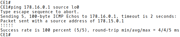
Picture 4: Testing Connectivity Between AS64501 and AS64502
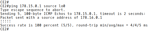
Picture 5: Testing Connectivity Between AS64502 and AS64501
3.2 Identifying BGP prefixes Requiring Preferential Treatment
In the event that we used BGP communities to identify the BGP prefix 172.15.0.0/16 (the one requiring preferential treatment), we would need to configure the PE1 router to tag the prefix with a BGP community. However, as we use the AS-PATH attribute to classify packets on edge routers, no configuration is needed.
3.3 Setting FIB policy entries based on the AS-PATH Attribute
PE-2 Configuration
When the prefix with special treatment is received from CE1, it contains the AS_PATH attribute set to 64501 (Picture 6). The prefix is propagated via iBGP within AS64500 to PE2.
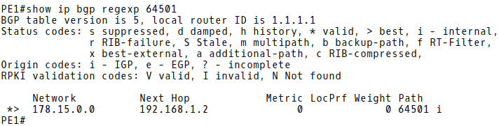
Picture 6: PE-1 BGP Table with Prefix 178.15.0.0/16 Received from eBGP Peer CE-1
The AS path access-list 10 is configured on PE2 to match 64501 in the AS_PATH attribute field. The regular expression is matching all routes originating in AS64501 (even when AS_PATH is prepended).
ip as-path access-list 10 permit ^(64501_)+$
The route-map QPPB-AS-PATH-RM is matching 64501 in the AS-PATH attribute field and is applied to mark qos-group as 10.
route-map QPPB-AS-PATH-RM permit 10
 match as-path 10
 set ip qos-group 10
| Note: QoS-group ID is a user-specified number that is assigned to a packet when such packet matches the user-specified criteria. The packet can then be classified based on this number. |
We will apply the policy in BGP using a table-map command in order to reflect it in the FIB of PE2.
 router bgp 64500
  table-map QPPB-AS-PATH-RM
The command show ip cef 178.15.0.0 shows that prefix is marked with the qos-group ID 10 (Picture 7).

Picture 7: Prefix 178.15.0.0/16 Marked with QoS group 10
3.4 Configuring Traffic lookup on Interface and Setting QoS policies
Packets have been marked in the FIB of PE2 but no packets will be marked until we configure PE2 to apply the policy to incoming traffic on an interface. This is done using bgp-policy interface command.
The policy will be applied for the incoming interface of the traffic (Gi0/3) to apply the policy for destination address of the traffic (178.15.0.0/16).
PE-2 Configuration
interface GigabitEthernet0/3
 bgp-policy destination ip-qos-map
3.5 Enabling Rate limit on Interface as Traffic is Received and Transmitted
Packets are now marked and we can set rate-limiting on the ingress port Gi0/3 using qos-group 10 which is applied at this port. The traffic rate will be limited to 5 Mbps (Picture 8).
interface GigabitEthernet0/3
 ip address 192.168.2.1 255.255.255.252
 rate-limit input qos-group 10 5000000 2500 2500 conform-action transmit exceed-action drop
 bgp-policy destination ip-qos-map
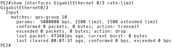
Picture 8: Rate-limit Set for GigabitEthernet0/3
The following output shows that when CE2 sends ICMP packets to 178.15.0.0/16 prefix, PE2 classifies this traffic based on the qos-group ID 10 and applies the rate-limit on traffic (Picture 9).
CE2# ping 178.15.0.1 source lo0 repeat 11999 timeout 0 size 1500
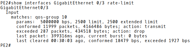
Picture 9: Traffic rate limited on Ingress Interface Gi0/3
Conclusion:
QPPB offers convenient classification and marking when BGP is already in use, overcoming the scalability issue of classifying based on ACLs, and the administrative problems of listing the networks that need premium services.