 Network Address Translation (NAT) was originally described in RFC 1631. Although initially presented as a short term solution for preventing the IPv4 addresses depletion, it is still being used. What is so special about NAT that makes network engineers use it for more than 26 years? Let’s find out.
1. NAT Advantages
The greatest benefit of NAT is that it slows down a process of IPv4 address space depletion. Thanks to NAT, private hosts on the inside network with an assigned private IPv4 address (RFC 1918) can communicate with public hosts on the Internet. In other words, organizations can assign the same private IPv4 address blocks defined in RFC1918 to the inside hosts while the hosts communicate outside the enterprise. Public address range assigned to an organization is then conserved as there is no requirement to allocate a public IP address to each host. NAT, along with the Classless Inter-Domain Routing (CIDR) has greatly extended the useful life of IPv4 addresses until their top-level exhaustion occurred on the 31st of January 2011.
2. Types of NAT
2.1 Static NAT
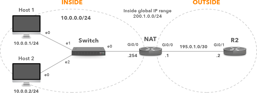
Static NAT mapps a private IP address to a public IP address. Static NAT does not save public IPv4 address. It is mainly used when a network device inside of a private network needs to be accessible from the Internet. We will explain and configure static NAT using a network topology presented below.
Routers R1 and R2 are iBGP neighbors in AS6400, peering with the IP addresses configured on the loopback interfaces. R1 however, is configured with the IP address 10.10.10.10 assigned from a private IP address range. Therefore, static NAT is configured on the NAT router to allow R2 to initiate a connection to R1, destination TCP port 179 (BGP). The IP address of BGP neighbor R1 in R2 configuration is therefore 195.0.1.1 (inside global address) instead of the private IP address 10.10.10.10. Remember, private IPv4 addresses are not routed in the public Internet (RFC 1918).
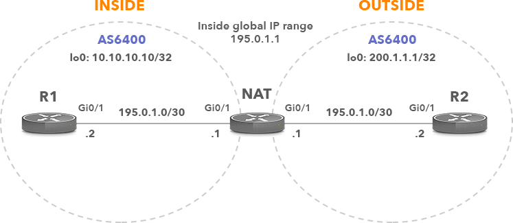
Picture 1: Static NAT and BGP
2.1.1 Static NAT Configuration
Router R1 Configuration
interface Loopback0
 ip address 10.10.10.10 255.255.255.255

interface GigabitEthernet0/0
 description Link to NAT
 ip address 10.0.0.2 255.255.255.252

router bgp 6400
 neighbor 200.1.1.1 remote-as 6400
 neighbor 200.1.1.1 update-source Loopback0
Static routes to support BGP adjacency.
ip route 200.1.1.1 255.255.255.255 10.0.0.1
Router R2 Configuration
interface Loopback0
 ip address 200.1.1.1 255.255.255.255

interface GigabitEthernet0/1
 description Link to NAT
 ip address 195.0.1.2 255.255.255.252
The IP address 195.0.1.1 is going to be translated to R1 BGP neighbor address 10.10.10.10 by NAT configured on the NAT router.
router bgp 6400
 neighbor 195.0.1.1 remote-as 6400
 neighbor 195.0.1.1 update-source Loopback0
NAT Router Configuration
Interface Gi0/0 is configured as an inside interface.
interface GigabitEthernet0/0
 description Link to R1
 ip address 10.0.0.1 255.255.255.252
 ip nat inside
Interface Gi0/1 is configured as an outside interface.
interface GigabitEthernet0/1
 description Link to R2
 ip address 195.0.1.1 255.255.255.252
 ip nat outside
The command ip nat inside source allows to inspect an incoming packet originated from an outside interface Gi0/1 towards an inside interface Gi0/0 and act accordingly.
Static routes to reach distant networks configured on the loopback interfaces.
ip route 200.1.1.1 255.255.255.255 195.0.1.2
2.1.2 Static NAT Verification
First, we will check if the BGP adjacency is established.
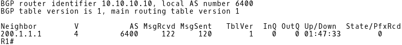
Picture 2: R1 BGP Neighbors
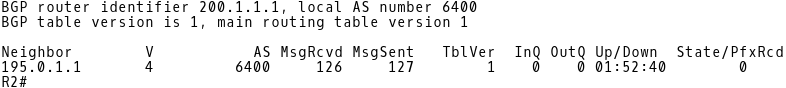
Picture 3: R2 BGP Neighbors
Finally, we will check the NAT table on the NAT router. The inside local address 10.10.10.10 TCP port 179 is translated to an inside global address 195.0.1.1 TCP port 179 (BGP). The source IP address inside the BGP OPEN message sent from R2 to R1 is 200.1.1.1 (outside global address) with the source TCP port 25956. The destination IP address is 195.0.1.1 with the destination TCP port 179. Only the TCP requests sent to 195.0.1.1 destination port 179 are translated to 10.10.10.10 destination TCP port 179. No other traffic sent from R2 to R1 is translated.

Picture 4: Router NAT Network Address Translation Table
2.2 Dynamic NAT
Dynamic NAT mapps a private IP address to a public IP address from a group of public IP addresses called the NAT pool. Dynamic NAT establishes a one-to-one mapping between a private IP address and a public IP address. The public IP address is taken from the pool of inside global addresses configured on the NAT router.
Picture 5: Enterprise with Dynamic NAT
2.2.1 Dynamic NAT Configuration
Router NAT Configuration
Interface Gi0/0 is configured as an inside interface.
interface GigabitEthernet0/0
 description Link to Switch
 ip address 10.0.0.254 255.255.255.0
 ip nat inside
Interface Gi0/1 is configured as an outside interface.
interface GigabitEthernet0/1
 description Link to R2
 ip address 195.0.1.1 255.255.255.252
 ip nat outside
Create a standard named ACL LOCALSUB matching the inside local addresses (10.0.0.0/24) that are going to be translated to the NAT pool MYPOOl.
ip access-list standard LOCALSUB
 permit 10.0.0.0 0.0.0.255
 deny any
Define NAT pool MYPOOL that matches the inside global IP range 200.1.0.0/24.
ip nat pool MYPOOL 200.1.0.1 200.1.0.254 netmask 255.255.255.0<
Define dynamic source NAT that translates subnets defined in the access-list LOCALSUB to the NAT pool MYPOOL.
ip nat inside source list LOCALSUB pool MYPOOL
Router R2 Configuration
interface GigabitEthernet0/1
 description Link to NAT
 ip address 195.0.1.2 255.255.255.252,/pre>
Static route to reach NAT subnet 200.1.0.0/24.
ip route 200.1.0.0 255.255.255.0 195.0.1.1,/pre>
2.2.2 Dynamic NAT Verification
Check NAT translation table on the router NAT after a successful login to the R2 router (195.0.1.2) from Host1 (10.0.0.1/24) and Host2 (10.0.0.2/24) using SSH.
NAT# show ip nat translations

Picture 6: Router NAT Network Address Translation Table
The inside local addresses 10.0.0.1 and 10.0.0.2 are translated to the inside global addresses 200.1.0.1 and 200.1.0.2, respectively.
2.3 Port Address Translation (PAT) or NAT Overload
PAT is a type of dynamic NAT which maps multiple private IP addresses to a single public IP. This is typically an IP address of the interface connected to an ISP. When a client from the inside network communicates to a host in the Internet, the router changes the source IP address (inside local address) to the inside global address and and changes a source port (TCP or UDP) number to the unique port number (there are 65535 port numbers available). These port mappings are kept in a NAT table. When the router receives a packet from the Internet, it checks this table and forwards the data packet to the original sender.
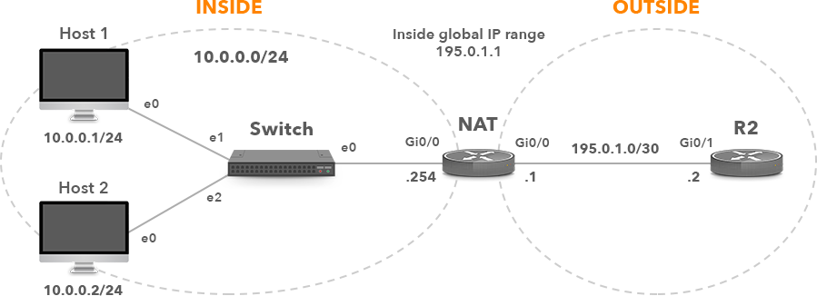
Picture 7: Enterprise with PAT
2.3.1 PAT Configuration
Router NAT Configuration
Interface Gi0/0 is configured as an inside interface.
interface GigabitEthernet0/0
 description Link to Switch
 ip address 10.0.0.254 255.255.255.0
 ip nat inside
Interface Gi0/1 is configured as an outside interface.
interface GigabitEthernet0/1
 description Link to R2
 ip address 195.0.1.1 255.255.255.252
 ip nat outside
Create a standard named ACL LOCALSUB matching a inside local addresses (10.0.0.0/24).
ip access-list standard LOCALSUB
 permit 10.0.0.0 0.0.0.255
 deny any
The inside local addresses will be translated to the IP address configured on the interface Gi0/1. Therefore, the inside global address may change in case an interface is configured with a dynamic IP address.
ip nat inside source list LOCALSUB interface GigabitEthernet0/1 overload
Router R2 Configuration
interface GigabitEthernet0/1
 description Link to NAT
  ip address 195.0.1.2 255.255.255.252
2.3.2 PAT Verification
We will check NAT translation table of the NAT router after a successful login to the router R2 (195.0.1.2) from Host1 (10.0.0.1/24) and Host2 (10.0.0.2/24) using SSH.
NAT# show ip nat translations
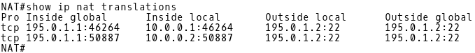
Picture 8: Router NAT Network Address Translation Table
Both inside local IP addresses 10.0.0.1 and 10.0.0.2 are mapped to a single inside global IP address 155.0.1.1, with different source TCP ports 42264 and 50887, respectively. PAT however, has not translated the source port for both connections. PAT configured on a Cisco router tries to keep the original source port from the inside private IP address. If this source port is already allocated to some other inside computer, PAT will allocate another port number.
3. NAT Drawbacks
It has commonly been assumed that NAT offers an additional level of security because it hides the internal network structure from the outside world. Clients located behind a router configured with NAT are visible under a global public address from the outside. However, clients can be identified by inspecting the application layer instead of the network layer (IPv4 addresses). For instance, they may be tracked based on the User-Agent ID inside the HTTP header while browsing the Internet.
One of the characteristics of NAT is that a new connection from the outside to the inside network cannot be initialized. NAT does not know how to forward packets. At the first glance, it seems to be a desired security feature. However, if an attacker tricks a user to install malware from a phishing email, he/she can gain access to the inside network, regardless of NAT. The attacker can access the inside network using a covert tunnel built from the inside to the outside. In this case, a firewall or IPS is the only security solution that can stop it.
The other drawback of NAT is that it breaks the end-to-end communication model. This happens because building connection from the outside to the inside network is prohibited. VOIP, IPSec host-to-host tunnels or peer-to-peer applications however rely on end-to-end communication model.
Moreover, NAT may add the undesired delay to communication. It may also cause excessive resource consumption (RAM, CPU) on devices where it is configured.
4. Multihoming with BGP and NAT tutorial
To better illustrate the NAT benefits we created a detailed tutorial covering the configuration of a multi-homed network design where a customer is connected to two different ISPs. Our tutorial describes a mechanism where source addresses of the internal users are translated to a different NAT address pool based on the selected path to the ISP. The design ensures continuous connectivity, eliminating ISP as a single point of failure.