 With the increasing popularity of multicast media applications, the monitoring of multicast traffic becomes more and more important. When it comes to NetFlow, it has been supporting unicast and multicast traffic as well, since the legacy version 5. However, as NetFlow v5 supports only ingress monitoring, it is not possible to determine how a flow is replicated to output interfaces. Therefore, all multicast packets may not be counted. As we will discuss later, an output interface is Null in case of ingress monitoring. For this reason, we will focus on the configuration of Flexible NetFlow v9 that allows egress monitoring as well. Furthermore, Flexible NetFlow allows service providers to collect and export parameters related to multicast traffic. This includes a replication factor and replicated packet/bytes.
What is Multicast routing and how does it Work?
IP Multicasting enables a host to send packets to a specific group of hosts. Hosts are called group members. Multicast Packets are delivered to group members that are identified by a single multicast group address. A group of hosts consists of both senders and receivers. Any host, regardless of whether it is a member of a group, can send multicast traffic to a group. However, only the group members can receive multicast messages.
Multicast routing is about building the forwarding trees from the sender to a group of receivers. There is only one path between every pair of routers, and the path is loop-free. In a Core-based tree, one router is selected as a Core or Rendezvous Point (RP) and all receivers build the shortest path to the core. The tree is shared by all senders. This concept assumes that members of the multicast group are sparsely distributed throughout the network and bandwidth is not necessarily widely available. The example of this multicast protocol is the PIM Sparse Mode (PIM-SM).
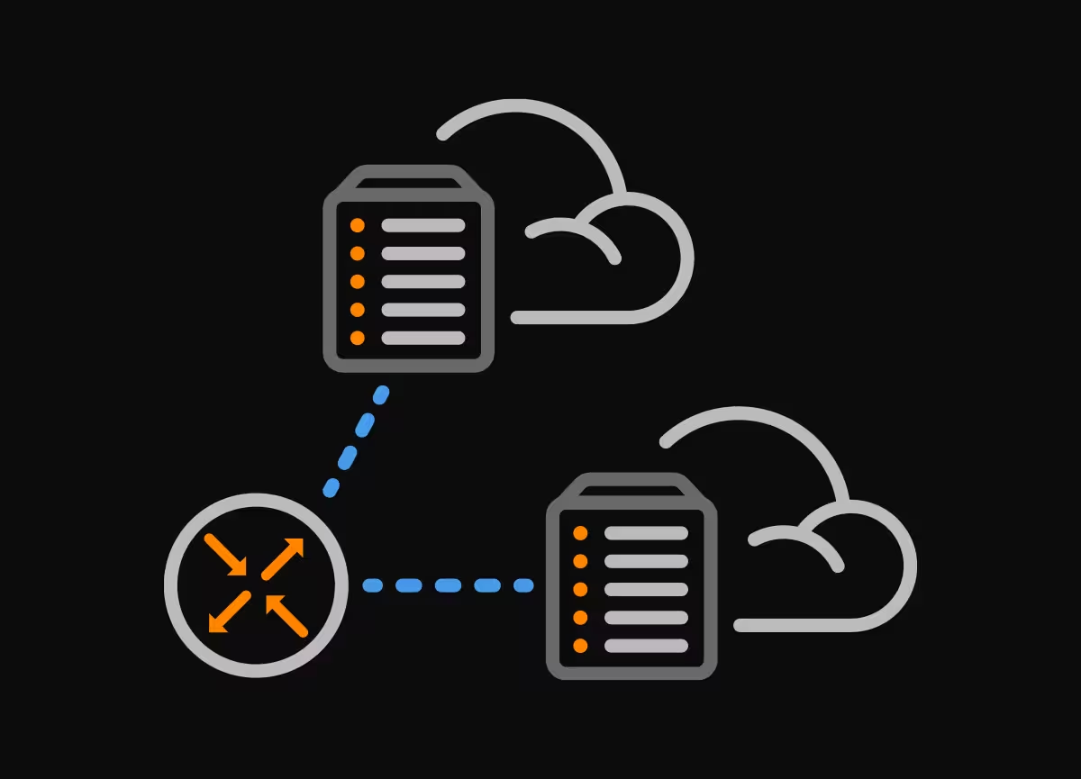
In our network, multicast traffic is streamed from a host Source by the VLC media player to the multicast address 239.0.0.2, port 5004 towards three listeners (Picture 1). They are dynamically registered to a multicast channel. All three listeners are also running VLC configured to open network stream rtp://239.0.0.2:5004.
The router R1 is configured as a Rendezvous Point (RP) for 239.0.0.2 multicast group. (Picture 2). R1 is also configured as a candidate BSR (Picture 3). RP distribution is enabled by using the PIM Bootstrap Router (BSR). As a result, other routers are notified via BSR about R1’s RP role. BSR sends messages on a hop-by-hop basis to 224.0.0.13 address with a local scope (TTL=1) informing all PIM neighbors about the RP address. This is the lo0 address of R1 (1.1.1.1) (Picture 2).
[vc_single_image image=”15549″ img_size=”full” alignment=”center”]
Picture 1: Multicast Network Topology with VLC Streaming Source and Three Listeners
[vc_single_image image=”15504″ img_size=”full” alignment=”center”]
Picture 2: Checking PIM Rendezvous Point (RP) Information
[vc_single_image image=”15505″ img_size=”full” alignment=”center”]
Picture 3: Checking Bootstrap router (v2) Information
Multicast Routing with PIM-Sparse Mode (BSR) Configuration
R1 Configuration
Firstly, enable multicast routing.
ip multicast-routing
Enable PIM Sparse Mode on interfaces.
interface Loopback0
 ip address 1.1.1.1 255.255.255.255
 ip pim sparse-mode

interface GigabitEthernet1/0
 ip address 192.168.1.2 255.255.255.0
 ip pim sparse-mode

interface GigabitEthernet2/0
 ip address 10.0.2.2 255.255.255.252
 ip pim sparse-mode

interface GigabitEthernet3/0
 ip address 10.0.3.2 255.255.255.252
 ip pim sparse-mode

interface GigabitEthernet4/0
 ip address 192.168.5.2 255.255.255.0

interface GigabitEthernet5/0
 ip address 10.0.4.2 255.255.255.252
 ip pim sparse-mode
Configure OSPF routing.
router ospf 1
 network 1.1.1.1 0.0.0.0 area 0
 network 10.0.2.0 0.0.0.3 area 0
 network 10.0.3.0 0.0.0.3 area 0
 network 10.0.4.0 0.0.0.3 area 0
 network 192.168.1.0 0.0.0.255 area 0
 network 192.168.4.0 0.0.0.255 area 0
 network 192.168.5.0 0.0.0.255 area 0
Allow R1 to send candidate rp advertisement to the BSR.
ip pim rp-candidate Loopback0
Configure R1 as candidate BSR.
ip pim bsr-candidate Loopback0 0
R2 Configuration
Configuration for all clients is similar, thus we will only show the configuration for the R2 router.
ip multicast-routing

interface Loopback0
 ip address 2.2.2.2 255.255.255.255
 ip pim sparse-mode

interface GigabitEthernet0/0
 ip address 192.168.2.2 255.255.255.0
 ip pim sparse-mode

interface GigabitEthernet0/1
 ip address 10.0.2.1 255.255.255.252
 ip pim sparse-mode

 router ospf 1
 network 2.2.2.2 0.0.0.0 area 0
 network 10.0.2.0 0.0.0.3 area 0
 network 192.168.2.0 0.0.0.255 area 0
Flexible NetFlow Configuration
The Flexible NetFlow (FnF) is the configuration interface on a device that allows users to configure and customize what information is exported in flow records using NetFlow version 9. Flexible NetFlow consists of 3 components.
1) Flow Record
2) Flow Exporter
3) Flow Monitor
Firstly, we will configure the NetFlow parameters for multicast. The statement below enables accounting for the number of bytes and packets forwarded.
R1(config)# ip multicast netflow output-counters
Ingress Multicast Accounting
Multicast ingress accounting provides information about the source and how many times the traffic was replicated.
Flow Record Configuration
The Flow Record serves as the basis for the NetFlow template used in the export process by specifying the information that we want to collect. The template contains key fields that are matched with match statement and non-key fields matched with the collect statements. All the key-fields matched with the match statement are collected as well.
Just as with traditional NetFlow v5, we match 7-tuple key fields with the match statements in order to identify the flow. This includes a source/destination address, source/destination transport layer port, IP Protocol, Type of Service (ToS), and the input interface port. A unique flow is created in a flow cache of the device if any of the key fields are matched. Flexible NetFlow (FnF) allows defining additional matching key fields. In addition to the 7-tuple key field, we match multicast traffic with the matching routing is-multicast statement. The flow match direction is matched, as well.
We also collect additional information that will be added to the Flow Record as non-key fields. They are specified by the collect statement. Like key-fields, no-key fields are exported with flows when configured with a collect statement. However, the non-key fields are not used to create or characterize flows, instead, they report flow parameters. In our example, we collect non-key fields such as interface output, packet, and bytes counters and timestamps.
Multicast replication factor and replicated packets/bytes are useful statistics in multicast accounting provided by Flexible NetFlow. The counter for replicated packets indicates the number of replicated packets to the output interfaces. Similarly, the counter for replicated bytes indicates the number of replicated bytes to the output interfaces. In our case, each input multicast packet is replicated by R1 to three output interfaces (Gi2/0, Gi3/0, and Gi5/0) towards Listeners 1, 2 and 3.
R1(config)# flow record MULTICAST-RECORD
R1(config-flow-record)# match ipv4 source address
R1(config-flow-record)# match ipv4 destination address
R1(config-flow-record)# match transport source-port
R1(config-flow-record)# match transport destination-port
R1(config-flow-record)# match ipv4 protocol
R1(config-flow-record)# match ipv4 tos
R1(config-flow-record)# match interface input
R1(config-flow-record)# match interface output
R1(config-flow-record)# match routing is-multicast
R1(config-flow-record)# match flow direction

R1(config-flow-record)# collect routing multicast replication-factor
R1(config-flow-record)# collect counter bytes
R1(config-flow-record)# collect counter packets
R1(config-flow-record)# collect counter bytes replicated
R1(config-flow-record)# collect counter packets replicated
R1(config-flow-record)# collect timestamp sys-uptime first
R1(config-flow-record)# collect timestamp sys-uptime last
R1(config-flow-record)# exit
Flow Export Configuration
Define the IP address of NetFlow collector and destination UDP port the collector is listening on.
R1(config)# flow exporter MULTICAST-EXPORTER
R1(config-flow-exporter)# description Flexible NetFlow version 9
R1(config-flow-exporter)# destination 192.168.4.1
R1(config-flow-exporter)# source GigabitEthernet0/3
R1(config-flow-exporter)# transport udp 2055
R1(config-flow-exporter)# exit
Flow Monitor Configuration
Assign flow record and exporter to the flow monitor.
R1(config)# flow monitor MULTICAST-MONITOR
R1(config-flow-monitor)# description Multicast Monitor
R1(config-flow-monitor)# exporter MULTICAST-EXPORTER
R1(config-flow-monitor)# record MULTICAST-RECORD
R1(config-flow-monitor)# exit
Interface Configuration for Flows
Activate the flow monitor that we created previously by assigning it to the interface in the ingress direction. In our example, both unicast traffic and multicast traffic are monitored. If you want to monitor multicast traffic only, add the multicast keyword.
R1(config)# interface gigabitEthernet0/0
R1(config)# ip address 192.168.1.2 255.255.255.0
R1(config)# ip flow monitor MULTICAST-MONITOR input
R1(config)# exit
When multicast flow accounting is enabled in the ingress direction, the destination interface on most flows is reported as Null (Picture 4). The replication factor specifies a source interface and IP address of the multicast traffic. It equals the number of output interfaces. In our case, the replication factor equals 0 instead of 3; the counters for replicated packets and bytes are 0 as well. This means that the feature is not supported by the platform configured as the router R1.
[vc_single_image image=”15518″ img_size=”full” alignment=”center”]
Picture 4: Multicast Record in R1 Flow Cache When Ingress Flow monitoring is Enabled on the Interface Gi1/0
| Note: The IP protocol 17 defines the UDP transport layer protocol. |
Ingress multicast NetFlow accounting does not increase the amount of NetFlow traffic exported to NetFlow collector. However, it lacks information about the output interface.
Egress Multicast Accounting
Multicast egress accounting monitors the destination of the traffic flow. For each replicated flow on the output interface a new multicast flow is created (Picture 3). The output interface is different so the statement “match interface output” is matched with each replicated flow. As a result, three unique flows with the same source interface (Gi1/0) are created. The output interface is the interface towards listeners.
interface GigabitEthernet2/0
 ip address 10.0.2.2 255.255.255.252
 ip flow monitor MULTICAST-MONITOR output
 ip pim sparse-mode

interface GigabitEthernet3/0End.
 ip address 10.0.3.2 255.255.255.252
 ip flow monitor MULTICAST-MONITOR output
 ip pim sparse-mode

 interface GigabitEthernet5/0
  ip address 10.0.4.2 255.255.255.252
  ip flow monitor MULTICAST-MONITOR output
  ip pim sparse-mode
[vc_single_image image=”15521″ img_size=”full” alignment=”center”]
Picture 5: R1 Flow Cache with Three Replicated Multicast Flows when Egress Flow monitoring is Enabled
If the NetFlow analyzer correlates flow information based on input and output interfaces only, it may wrongly assume that those three replicated multicast flows enter the router R1 via the interface Gi1/0. As a result, NetFlow analyzer can determine three times higher throughput for Gi1/0 than it really is as only a single multicast flow enters R1 via Gi1/0. As a workaround, we can enable ingress multicast accounting on the interface Gi1/0. This allows the NetFlow analyzer to obtain a more accurate picture of the replication of multicast flows (Picture 6). This approach, however, can lead to faster flow cache exhaustion and higher bandwidth utilization due to the increased amount of NetFlow data being exported towards collectors.
interface GigabitEthernet1/0
 ip address 192.168.1.2 255.255.255.0
 ip flow monitor MULTICAST-MONITOR input
 ip pim sparse-mode
[vc_single_image image=”15523″ img_size=”full” alignment=”center”]
Picture 6: R1 Flow Cache with Multicast Flow when Ingress Flow monitoring is Enabled
Conclusion:
The accuracy of NetFlow multicast traffic monitoring and accounting can be greatly improved by a collection of multicast related non-key fields that are available in Flexible NetFlow v9. Those are replication factor and replicated packets/bytes. Moreover, NetFlow v9 allows egress (output) monitoring, so we can safely determine how a multicast packet is replicated to interfaces. Service providers and content/application providers may utilize the information for more accurate billing. However, a Netflow analyzer must be able to support these multicast non-key fields to calculate the correct network utilization and application resource usage.