 One of the characteristics of MPLS TE is that an established LSP (label Switched Path) is not torn down in the event of a bandwidth increase process failure (RFC3209). LSP is “out of profile,” so it is not following the traffic engineering parameters that were set up for it. When LSP is out of profile, it may result in degraded performance and traffic loss.
Moreover, this can cause issues when there is an increase in bandwidth demand on one LSP that is sharing links with other in-profile LSPs that are not aware of the demand increase. If the increase in demand cannot be satisfied by other links, the affected LSP may stay on the same path, causing congestion and affecting other in-profile LSPs that share the same link.
Suppose we have a network topology where two routers, R1 and R2, are connected by a single link. Let’s assume we have two LSPs, LSP1 and LSP2, that traverse this link. Both LSPs require a certain amount of bandwidth to operate properly.
Let’s assume that the traffic demand on LSP1 suddenly increases, resulting in a situation where LSP1 requires more bandwidth than what is available on the link between R1 and R2. At the same time, LSP2 is still active and is also using the link.
As a result, LSP1 and LSP2 are now in a deadlock situation. LSP1 is waiting for more bandwidth to become available on the link, but LSP2 is already using the available bandwidth and cannot release it until it has completed its transmission. Similarly, LSP2 cannot proceed until LSP1 releases some of the bandwidth it is using.
In this scenario, LSP1 and LSP2 are deadlocked and cannot make any progress until the deadlock is resolved. If the deadlock persists, both LSPs may fail to transmit data, which can result in severe network performance issues.
In distributed MPLS traffic engineering, we can use a combination of Auto-Bandwidth and LSP Priority to prevent deadlock.
1. Auto-Bandwidth
Let’s say we have an LSP that is experiencing congestion due to an increase in traffic demand. With Auto-Bandwidth enabled, the LSP’s bandwidth allocation can be automatically adjusted to match its actual traffic demand. This can help prevent the LSP from exceeding the available bandwidth and causing congestion on the network, which can lead to deadlock.
This solution is easy to implement because auto-bandwidth is configured on the routers. In other words, routers calculate the bandwidth value by periodically measuring how much traffic is actually forwarded over the LSPs.
2. MPLS TE Tunnel Priorities
Suppose we have two LSPs traversing the same link, but one of them is carrying more critical traffic than the other. By assigning a higher priority level to the critical LSP, we can ensure that it receives preferential treatment in the event of congestion. This can help prevent the critical LSP from getting stuck in a deadlock situation and ensure that it continues to transmit data.
Imagine a network with three LSPs: LSP A, LSP B, and LSP C. These LSPs share a common path between two nodes, and the available bandwidth on the shared path is 100 Mbps. The current bandwidth usage is as follows:
LSP A (priority 1): 30 Mbps
LSP B (priority 2): 40 Mbps
LSP C (priority 3): 20 Mbps
Now, let’s say the bandwidth demand for LSP A suddenly increases to 50 Mbps. Without LSP priority, this increase in demand could lead to a deadlock, as there would not be enough bandwidth to accommodate the new requirement. However, since LSP priority is in place, the network will take the following steps to resolve the issue:
The network attempts to find an alternate path for LSP A with sufficient bandwidth. If an alternate path is found, the LSP is rerouted, and the deadlock is avoided.
If no alternate path is found, the network checks whether preemption can be applied to free up resources. In this case, LSP A has a higher priority than LSP B and LSP C. Therefore, LSP C (lowest priority) will be preempted, freeing up 20 Mbps of bandwidth. Now, LSP A can accommodate the increased bandwidth demand without causing a deadlock.
In this example, LSP priority helped avoid MPLS TE deadlock by allowing the higher-priority LSP to claim the necessary resources, either by finding an alternate path or preempting lower-priority LSPs.
Note: There are 8 setup priorities and hold priorities, 0 to 7, where 0 is the most preferred and 7 is the least preferred (default). The setup priority determines the importance of bringing up a tunnel, while the hold priority determines the importance of keeping a tunnel operational.
However, if there is not enough available bandwidth, priorities come into play. The setup priority of the new tunnel is compared to the hold priority of existing tunnels, and if the setup priority is higher, it can preempt an existing tunnel.
3. Configuration Headend Tunnel – PE1
mpls traffic-eng tunnels
The frequency keyword specifies the interval, in seconds, for sampling the output rate of each tunnel configured for automatic bandwidth. In our case, one sample is collected every ten seconds.
mpls traffic-eng auto-bw timers frequency 10
Frequency (adjust interval) 300 enables automatic bandwidth adjustment for the tunnel and controls the manner in which the bandwidth for a tunnel is adjusted. So, after 300 seconds, the highest collected bandwidth sample from all collected 30 samples (300 seconds / 10 seconds = 30 samples) is used to adjust bandwidth.
The max bandwidth for the tunnel is 4000 kbps.
We also set both tunnel setup and hold priorities to 2. The most common configuration is to set the same value for the setup and the hold priority. When holding priority is 0, the tunnel will never get preempted once established.
interface Tunnel12
  ip unnumbered Loopback0
  load-interval 30
  tunnel mode mpls traffic-eng
  tunnel destination 8.8.8.8
  tunnel mpls traffic-eng priority 2 2
  tunnel mpls traffic-eng bandwidth 50
  tunnel mpls traffic-eng path-option 1 dynamic
  tunnel mpls traffic-eng auto-bw frequency 300 max-bw 4000

interface Loopback0
 ip address 2.2.2.2 255.255.255.255

 interface GigabitEthernet1
 ip address 20.20.20.1 255.255.255.252
 negotiation auto
 mpls traffic-eng tunnels
 no mop enabled
 no mop sysid
 ip rsvp bandwidth 1024 1024

router ospf 1
 router-id 2.2.2.2
 network 2.2.2.2 0.0.0.0 area 0
 network 20.20.20.0 0.0.0.3 area 0
 mpls traffic-eng router-id Loopback0
 mpls traffic-eng area 0
The command below displays information about tunnel12, including automatic bandwidth information for tunnels, priority, etc. (Figure 1).
PE1# show mpls traffic-eng tunnels tun12
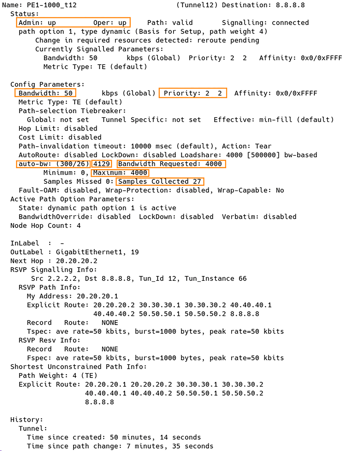
Figure 1 – Checking MPLS TE Tunnel 12 Parameters
300 is the time, in seconds, between bandwidth adjustments.
26 is the time, in seconds, remaining until the next bandwidth adjustment.
4129 is the largest bandwidth sample since the last bandwidth adjustment.
4000 is the last bandwidth adjustment and the bandwidth currently requested for the tunnel.
27 is the number of samples collected
Note: In the output of the command, the largest bandwidth sample is 4129 out of the 26 samples collected so far. However, the maximum bandwidth for the tunnel is limited to 4000 kbps by the configuration, so after 26 seconds, the requested bandwidth is set to 4000.
Conclusion
MPLS TE networks may suffer deadlocks due to LSPs exceeding available bandwidth. We have discussed two solutions to this problem: Auto-Bandwidth and LSP Priority.
With Auto-Bandwidth, the network adjusts the bandwidth allocation of an LSP to match its actual traffic demand and prevent congestion.
LSP Priority assigns higher priority levels to critical LSPs to ensure they receive preferential treatment in the event of congestion. We have also provided an example of how LSP Priority can prevent deadlocks by allowing higher-priority LSPs to claim necessary resources.
The article presents configuration commands for headend tunnels and explains how to check MPLS TE tunnel parameters.