 The Internet consists of Internet Service Providers (ISPs) of all shapes and sizes. ISPs have two options when it comes to connecting to the Internet. They can either purchase IP transit from an upstream provider, or form a peering relationship with other ISPs. To achieve the best balance between cost and performance, ISPs very often use a combination of these two options.
Peering
In the peering relationship ISPs exchange routing information and network traffic in order to provide access to their customers’ networks. However, only customer prefixes are exchanged; prefixes received from the upstream provider are not advertised to the peers.
There is no charge for traffic exchanged between ISP peers as they do not pay the upstream provider to interconnect their customer’s networks. This is what we call settlement-free peering. The ISPs pay only for the port on the fabric at the public peering point (IXP) or, in the case of private peering, share the cost of the circuit. The volume of IP transit data is therefore reduced and hence the cost.
IP Transit
Unlike peering, IP transit is a paid service whose price is determined by bandwidth usage, which can be metered using the 95th traffic percentile method. The role of a transit provider, also called an upstream provider, is to connect a customer’s network or downstream ISP to the global Internet. To do this, the transit provider allows the customer traffic to pass through its network so that it can reach all possible destinations on the Internet.
IP transit service is BGP-based, so customers who buy IP transit must operate their own Autonomous System (AS). Customers receive a full BGP Internet table that includes:
- prefixes of other customers of the upstream provider;
- prefixes advertised by ISP peers of the upstream provider;
- prefixes received by upstream provider from its upstream providers.
Tier-1, Tier-2 and Tier-3 Service Providers
ISPs are organized into a hierarchical structure that consists of three tiers.
Tier-1 Service Providers
Tier 1 transit providers have a global reach and they are the backbone of the Internet. They do not buy transit service, and they peer with each other at zero cost. Tier-1 networks connect Tier-2 and Tier-3 (lower tiers) ISPs and they charge lower tier ISPs to allow traffic to transit their networks.
Tier-2 Service Providers
Tier 2 providers have large networks and a wide global presence. Tier 2 providers peer with each other to reduce costs associated with IP transit but they also need to buy IP transit from Tier 1 providers.
Tier-3 Service Providers
Tier-3 ISPs are local providers with national reach. They usually buy IP transit from Tier-2 providers to avoid expensive Tier-1 IP transit. Tier-3 providers are typically without any transit customers and have no peering connections.
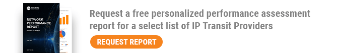
The interconnection of Tier-1, 2 and 3 service providers is illustrated in Figure 1. The transit connection is indicated by a solid line, while the dotted line is used for peering. Traffic from the lower-tier ISP to a higher-tier provider is called going upstream. Similarly, traffic from the Internet and destined to the lower-tier ISP is called going downstream.
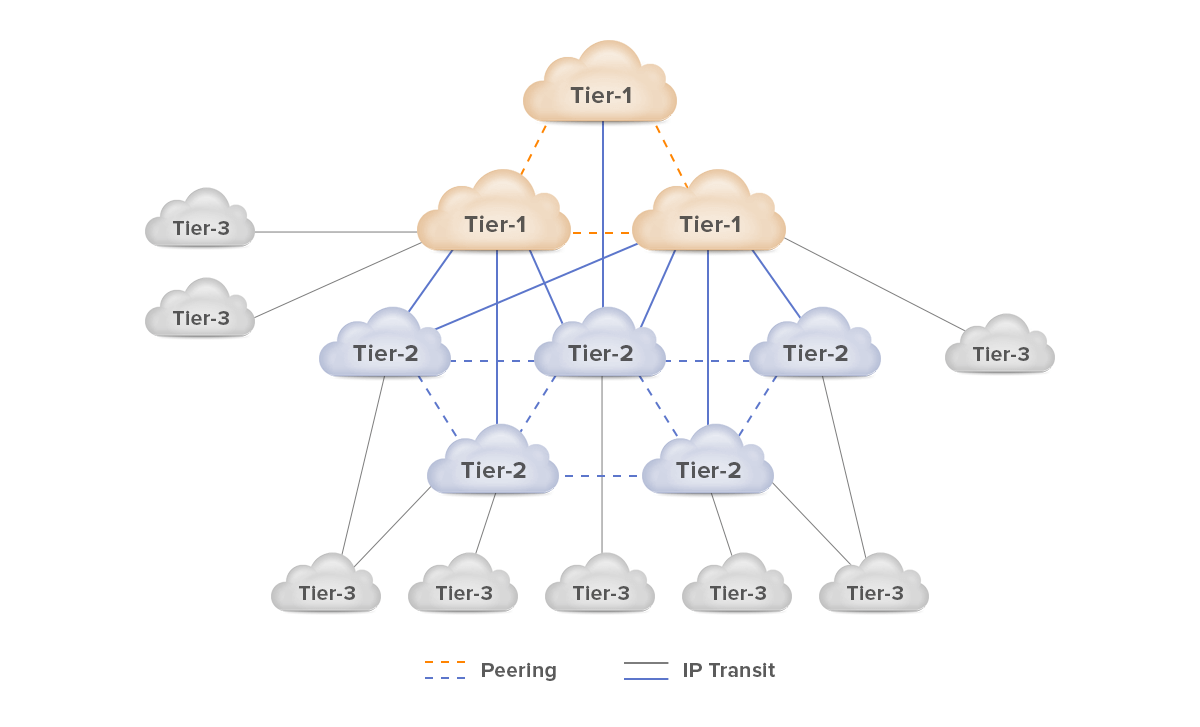
Figure 1 – Tier-1, Tier-2 and Tier-3 Internet Service Providers
Let’s discuss several network topologies that define how a customer is connected to an upstream provider.
Single-Homed Network Topology
The most straightforward design is single-homed, where the customer has a single connection to only one upstream provider (Figure 2). The ISP only announces a default route to the customer; BGP is not needed because there is only one exit path to the Internet. This is the most cost-effective solution with a simple routing policy. The disadvantages are obvious; if the link or router fails, the customer’s entire Internet connection will also fail.
Figure 2 – Single-Homed Design
Dual-Homed Network Topology
A network is dual homed if there is more than one connection to one upstream provider (Figure 3). A customer is protected against a link failure, but the device still represents a single point of failure.
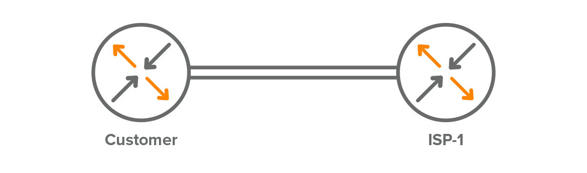
Figure 3 – Dual-Homed Design
We can add another router on the ISP side and connect the customer’s router to the provider’s routers (Figure 4). The failure of one of the ISP routers will have no effect on the customer connection, but the customer-side device still represents a single point of failure.
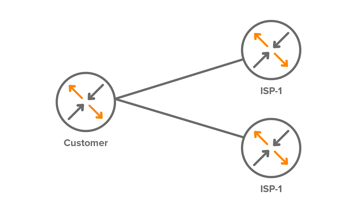
Figure 4 – Dual-Homed Design with Two ISP Devices
Redundancy on the customer side can be further improved by adding another router to the topology (Figure 5).
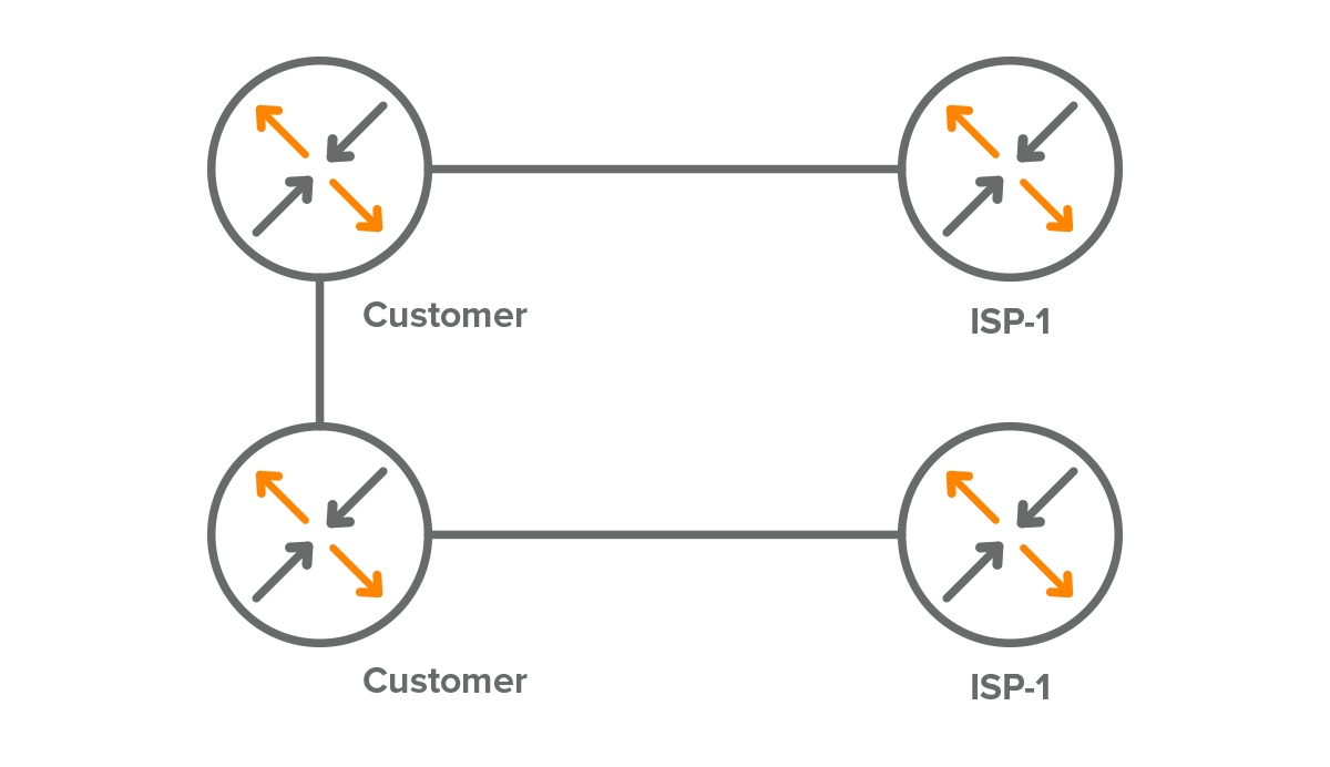
Figure 5 – Dual-Homed Design with Redundant Devices
Single Multi-Homed Network Topology
We speak about multi-homed connections when the customer is connected to two different upstream providers (Figure 6). Unlike single-homed design, multi-homed topology provides the highest redundancy, reliability, and efficiency.
Redundancy
The customer is protected from the failure of an upstream provider. When a connection to one of the providers fails, traffic is sent over another link to the second upstream ISP within seconds.
Reliability
Traffic from the Internet to the customer’s mission-critical applications is also secured because customer prefixes are advertised by at least one of the upstream providers.
Efficiency
The customer can configure custom BGP routing policies to manipulate BGP path attributes to prioritize one of the links for both outbound and inbound network traffic.
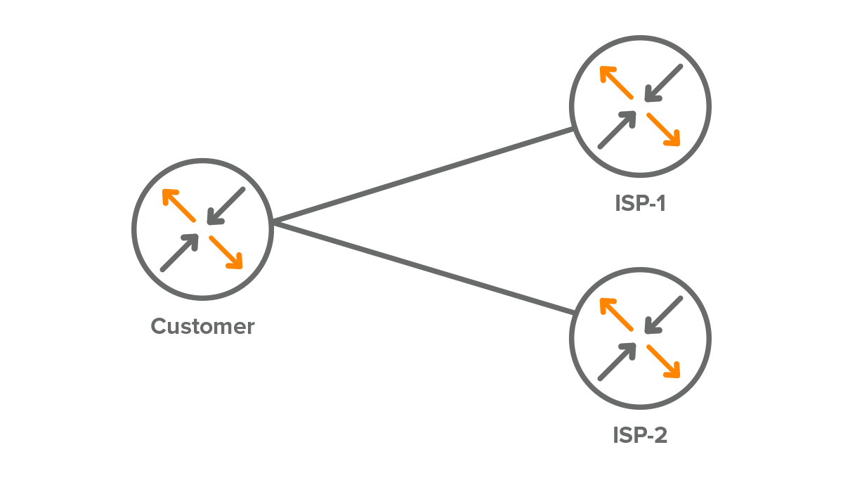
Figure 6 – Single Multi-Homed Design
We only have one router at the customer, so we can improve the redundancy by adding a second router on the customer side.
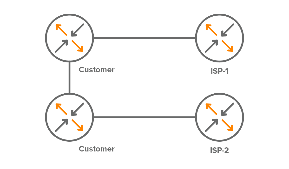
Figure 7 – Single Multi-Homed with Redundant Devices
Dual Multi-Homed Network Topology
The redundancy of the single multi-homed design can be improved by adding additional links between a customer and ISPs. If one of the links fails, Internet connectivity through the same ISP is maintained using the backup link (Figure 8).
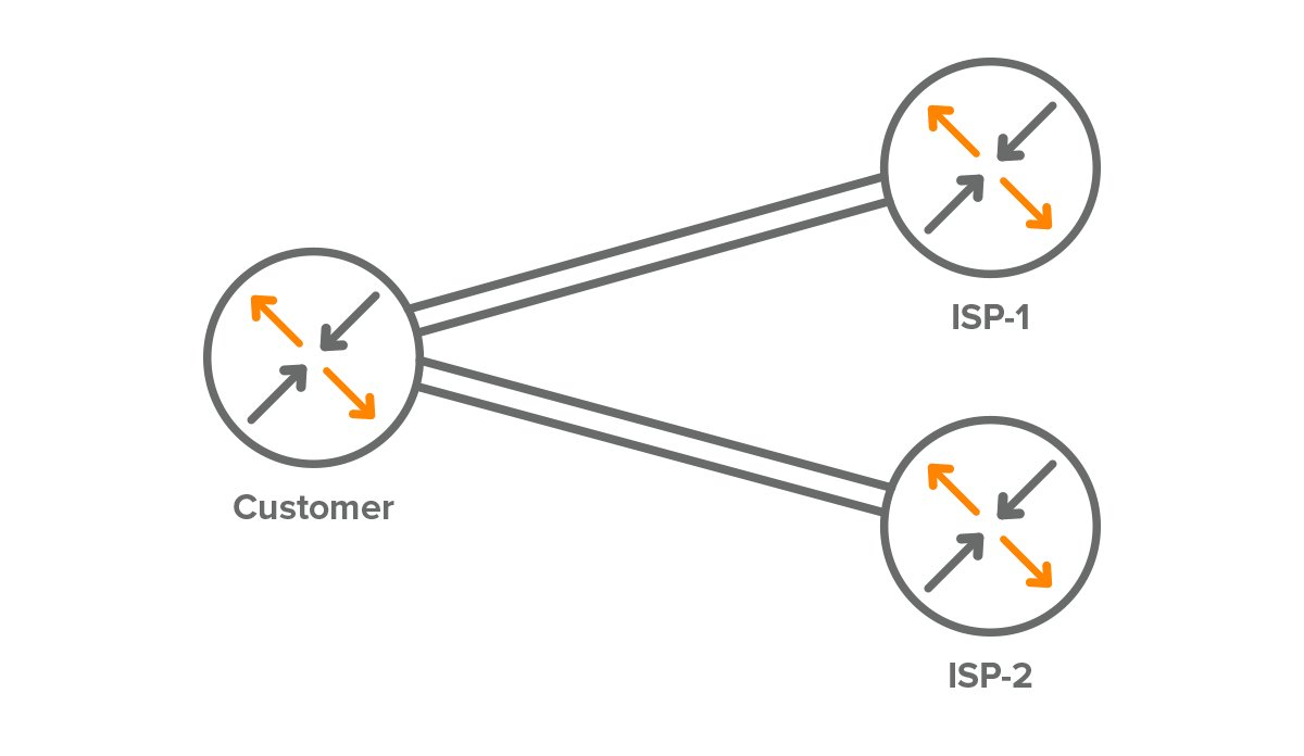
Figure 8 – Dual Multi-Homed Design
The design shown in Figure 9 provides the highest redundancy of links, customers and ISPs, but is also the most expensive solution.
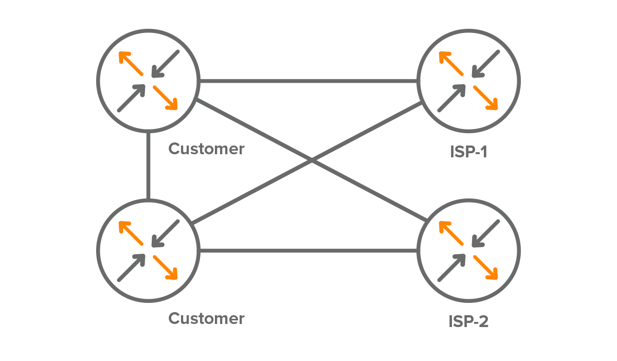
Figure 9 – Dual Multi-Homed Design with Redundant Customer and ISP Devices
Conclusion
Understanding ISP interconnection ensures that organizations choose the most cost- and technically effective solution that meets their business needs before actually purchasing an IP transit service.
The Noction Intelligent Routing Platform helps service providers and enterprises that operate a multihomed network environment to improve BGP routing performance.
For more information about IRP, see the FAQ section or contact us. We are happy to answer any questions or deploy a test installation in your infrastructure to automate BGP routing and provide you with reports on your network performance, providers issues, outages, etc.