Understanding BGP states is essential to grasp how BGP operates. Similar to interior...


Request a personalized demo/review session of our Intelligent Routing Platform

Evaluate Noction IRP, and see how it meets your network optimization challenges

Schedule a one-on-one demonstration of our network traffic analysis product

Test drive NFA today with your own fully featured 30-day free trial
 In this blog post we are going to explain how Generic Routing Encapsulation (GRE) tunnel might be used in a situation when the Border Gateway Protocol (BGP) speaking routers are connected via the non BGP-speaking routers. We will also discuss the problems with MTU size reduction due to tunnels and the Path MTU discovery technique, as well as possible issues with recursive routes through a tunnel.
Let’s take a look at the following basic scenario:
Company A runs Cisco routers CE1, Core1 and CE2 and is a customer of two Internet Service Providers (ISPs) – ISP1 and ISP2. The company is assigned an Autonomous System Number (ASN) 64500 and the BGP is enabled on its routers CE1 and CE2. The router CE1 is connected to the router PE_ISP1 (ASN 64501) and the router CE2 is connected to the router PE_ISP2 (ASN 64502). In addition to the BGP routing protocol, Open Shortest Path First (OSPF) is enabled on all company routers.
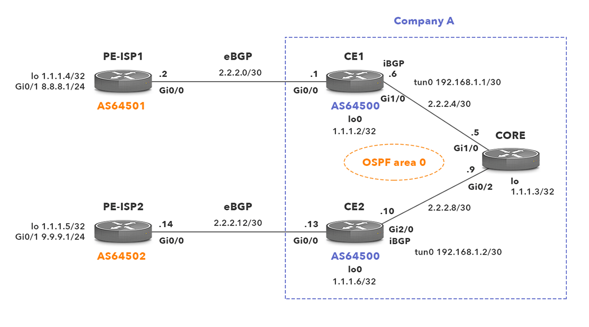
Picture 1 – Network topology
Let’s check the configuration of the two ISP routers.
The two ISP routers contain the basic BGP configuration that is needed to establish an eBGP session with CE1 and CE2 in AS 64500. The ISPs and the customer routers peer using their loopback IP addresses. Therefore, the command update-source Loopback0 is used in BGP configuration. In addition to that, a static route on the providers’ and customers’ routers towards their eBGP peers must be configured to initiate the eBGP peer session.
The command disable-connected-check is required on both ISPs and customer routers. It disables the connection verification process for eBGP peering sessions that are reachable by a single hop but are configured on a loopback interface.
The redistribute connected command does what it says. It redistributes all connected routes via the BGP protocol.
router bgp 64501
bgp router-id 1.1.1.4
bgp log-neighbor-changes
redistribute connected
neighbor 1.1.1.1 remote-as 64500
neighbor 1.1.1.1 disable-connected-check
neighbor 1.1.1.1 update-source Loopback0ip route 1.1.1.1 255.255.255.255 2.2.2.1interface Loopback0
ip address 1.1.1.4 255.255.255.255interface GigabitEthernet0/0
description Link to CORE AS64500
ip address 2.2.2.2 255.255.255.252
interface GigabitEthernet0/1
ip address 8.8.8.1 255.255.255.0
router bgp 64502
bgp router-id 1.1.1.5
bgp log-neighbor-changes
redistribute connected
neighbor 1.1.1.2 remote-as 64500
neighbor 1.1.1.2 disable-connected-check
neighbor 1.1.1.2 update-source Loopback0ip route 1.1.1.2 255.255.255.255 2.2.2.13interface Loopback0
ip address 1.1.1.5 255.255.255.255interface GigabitEthernet0/0
description Link to CE2 AS64500
ip address 2.2.2.14 255.255.255.252
interface GigabitEthernet0/1
ip address 9.9.9.1 255.255.255.0
Customer’s CE1 and CE2 routers are BGP peers with the providers’ routers. In addition, the routers CE1 and CE2 are configured to establish internal BGP (iBGP) neighborship to each other. To change the next hop attribute from 1.1.1.4 to 1.1.1.1 for the BGP advertisement sent from CE1 to CE2, we must add the command neighbor 1.1.1.2 next-hop-self to the BGP configuration of the CE1 router. If not, the router CE2 would not add the routes with the next hop 1.1.1.4 to its routing table as it does not have a route to the network 1.1.1.4/32 in its routing table. A similar command must be added under BGP configuration of the CE2 to configure CE2 router as a next hop (1.1.1.2) for advertisement received from ISP2 and sent towards CE1.
As we have mentioned before, the OSPF protocol is enabled on routers CE1, Core and CE2. To prevent sending OSPF hello messages towards ISP routers, the command passive-interface GigabitEthernet0/0 is configured under OSPF protocol configuration.
router bgp 64500
bgp router-id 1.1.1.1
bgp log-neighbor-changes
redistribute connected
neighbor 1.1.1.2 remote-as 64500
neighbor 1.1.1.2 update-source Loopback0
neighbor 1.1.1.2 next-hop-self
neighbor 1.1.1.4 remote-as 64501
neighbor 1.1.1.4 disable-connected-check
neighbor 1.1.1.4 update-source Loopback0ip route 1.1.1.4 255.255.255.255 2.2.2.2interface Loopback0
ip address 1.1.1.1 255.255.255.255interface GigabitEthernet0/0
description Link to PE-ISP1 AS64501
ip address 2.2.2.1 255.255.255.252
interface GigabitEthernet1/0
description Link to CORE
ip address 2.2.2.6 255.255.255.252
router ospf 1
router-id 1.1.1.1
passive-interface GigabitEthernet0/0
network 1.1.1.1 0.0.0.0 area 0
network 2.2.2.0 0.0.0.3 area 0
network 2.2.2.4 0.0.0.3 area 0
router bgp 64500
bgp router-id 1.1.1.2
bgp log-neighbor-changes
redistribute connected
neighbor 1.1.1.1 remote-as 64500
neighbor 1.1.1.1 update-source Loopback0
neighbor 1.1.1.1 next-hop-self
neighbor 1.1.1.5 remote-as 64502
neighbor 1.1.1.5 disable-connected-check
neighbor 1.1.1.5 update-source Loopback0ip route 1.1.1.5 255.255.255.255 2.2.2.14interface Loopback0
ip address 1.1.1.2 255.255.255.255interface GigabitEthernet0/0
description Link to PE-ISP2 AS64502
ip address 2.2.2.13 255.255.255.252
interface GigabitEthernet2/0
description Link to CORE
ip address 2.2.2.10 255.255.255.252
router ospf 1
router-id 1.1.1.2
passive-interface GigabitEthernet0/0
network 1.1.1.2 0.0.0.0 area 0
network 2.2.2.8 0.0.0.3 area 0
network 2.2.2.12 0.0.0.3 area 0
In this part we will discuss where the GRE tunnel configuration is in our scenario. Let’s check a routing table on the router PE-ISP2 first.
As we see the router PE-ISP2 successfully put all the presented networks into its routing table. However ping from PE-ISP2 to 8.8.8.1 does not work. When we enable debugging of ICMP packets with debug ip icmp command on the Core router we will see the following message.
The error message reveals that the Core router does not know where to send a packet destined for the IP address 8.8.8.1. It also sends ICMP message back to the PE-ISP2 router. There are several solutions to this problem. For instance, we can redistribute BGP routes into OSPF protocol on routers CE1 and CE2. Another solution would be to enable BGP on the Core router and peer it with CE1 and CE2 routers. Since we want to discuss the GRE tunnel usage in our scenario we will focus on the second one. First we are going to configure tunnel interfaces on CE1 and CE2 routers.
| Note: We do not need to put the command tunnel mode gre ip into the tunnel configuration as it is a default mode for a tunnel interface. |
CE1
CE2
At this point the tunnel interface is up and we should be able to ping between tunnel IP addresses. The next step is the reconfiguration of CE1 and CE2. We will configure them to set a particular tunnel IP address as a next-hop path attribute for Network Layer Reachability Information (NLRI) received in BGP update messages. We will create a route-map on CE1 router that changes the next-hop IP address 1.1.1.1 to 192.168.1.1 for updates sent towards the router CE2. Afterwards we will apply the route map for the iBGP neighbor 1.1.1.2.
CE1
A brief look at the BGP table for route 8.8.8.0 on the CE2 router proves that a tunnel interface IP 192.168.1.1 is now used as the next hop for the route 8.8.8.0/24.
We will do the same in the opposite direction on the CE2 router.
CE2
Let’s check the next-hop for the route 9.9.9.0/24 on the CE1 router.
Now we should be able to ping from ISP2 to ISP1 and vice versa.
And the output from the traceroute command follows.
The maximum length of an IP packet can be 65 535 bytes. It includes 20 Bytes of IP header plus 65515 Bytes of payload. However the smaller size of IP packet is normally used on links depending on the type of layer 2 protocol. This length is set by the Maximum Transmission Unit (MTU) value. In other words, the MTU says how much data the sending host can put into a packet.
MTU for Ethernet Link is 1500 Bytes, not including the Ethernet header and trailer. It includes 20 Bytes for TCP header, 20 Bytes for IP header and there are 1460 Bytes left for payload. Once a tunnel interface is created, MTU for the tunnel interface is automatically set to the 1476 Bytes. It is set to this value because the GRE tunnel overhead is 24 Bytes.
If the packet with MTU more than 1476 Bytes is received, a router needs to fragment this packet into small chunks. Those chunks have MTU set to 1476 Bytes and they are sent with this MTU over the GRE tunnel. The downside of fragmentation is obvious – a router has to generate new headers and it takes its resources (CPU and memory) plus additional requirements for bandwidth. On the other side of the GRE tunnel, router reassemble chunks into an original full size packet.
The configured MTU on the path from point A to point B can be quickly tested with the ping command with no fragmentation set and using selected MTU.
PE-ISP1# ping 9.9.9.1 df-bit size 1477
*Apr 25 21:38:39.926: ICMP: dst (2.2.2.2) frag. needed and DF set unreachable rcv from 2.2.2.1 mtu:1476.M
The ICMP message received on PE-ISP1 says that a router with IP address 2.2.2.1 (CE1) has the MTU set to 1476 Bytes on one of its links. However we strictly disallow fragmentation so the ping command is not successful.
The question appears: Why a router bothers to send an ICMP message back to the sending host?
In case DF (Don’t fragment) flag is set to 1, a router is not allowed to fragment a packet. If the packet exceeds 1476 Bytes, ICMP message type 3 Destination unreachable and code 4 Fragmentation needed is sent to the sending host, containing the information about MTU of next hop 1476 Bytes. The sending host learns this information and sets MTU to 1476 Bytes. This mechanism is called Path MTU Discovery (PMTUD) and is described in RFC 1191. PMTUD is supported by TCP and UDP protocols and it is commonly enabled on the hosts with DF bit set to 1. Thanks to PMTUD a sending host sets the correct MTU (the lowest on a link) and the packets do not get fragmented.

The problem occurs when ICMP messages are blocked somewhere on the path by an access-list. A router with configured lower MTU than the one of a sent IP packet sends ICMP Destination Unreachable, Fragmentation needed message back to the sending host. However the sending host cannot receive it and learn the correct MTU. The sending host keeps using DF set to 1 in IP headers of the sent packets. As a result, the router with the configured lower MTU on the link represents an MTU bottleneck on the path. Since it is not allowed to fragment packets, the connection fails.
Recursive routing certainly represents an unwanted issue. It occurs when a router tries to route to the tunnel destination address using the tunnel interface itself. Once a router recognizes a recursive routing, it willingly shuts down a tunnel interface for a certain period of time. Afterwards the tunnel interface is brought back up by the router and the process happens again. As a result, the tunnel interface OSPF and BGP routes are flapping.
In order to simulate recursive routing, we will enable OSPF protocol on tunnel interfaces of CE1 and CE2 routers.
Now we will check OSPF neighbors.
CE1# show ip ospf neighbor
Neighbor ID Pri State Dead Time Address Interface
1.1.1.2 0 FULL/ – 00:00:34 192.168.1.2 Tunnel0
1.1.1.3 1 FULL/DR 00:00:38 2.2.2.5 GigabitEthernet1/0
CE2# show ip ospf neighbor
Neighbor ID Pri State Dead Time Address Interface
1.1.1.1 0 FULL/ – 00:00:36 192.168.1.1 Tunnel0
1.1.1.3 1 FULL/DR 00:00:32 2.2.2.9 GigabitEthernet2/0
There are two OSPF neighbors presented in the command output. The first OSPF adjacency is formed over the tunnel interface and the second one is formed over Gigabit Ethernet interface. So far, the routing table of the CE1 router does not contain any recursive routes. All the OSPF routes are learned over the interface GigabitEthernet1/0.
Let’s investigate the OSPF cost for the tunnel and Gigabit Ethernet interfaces on the CE1 router
The Gigabit Ethernet interface is preferred over tunnel interface by OSPF protocol since its cost is 1 compared to the cost 1000, generated for the tunnel interface. To simulate recursive routing we need to modify cost of the tunnel interface to 1 on both CE routers.
After a while we can see the following log messages.
*May 1 18:44:51.911: %ADJ-5-PARENT: Midchain parent maintenance for IP midchain out of Tunnel0 – looped chain attempting to stack
*May 1 18:44:59.095: %TUN-5-RECURDOWN: Tunnel0 temporarily disabled due to recursive routing
*May 1 18:44:59.095: %LINEPROTO-5-UPDOWN: Line protocol on Interface Tunnel0, changed state to down
From this point the tunnel interface and routing tables of routers CE1 and CE2 are flapping indefinitely. Some routes in the routing table of CE1 are now available through the tunnel interface.
What does exactly happen? We will explain it in the following example.
Previously, we enabled OSPF protocol on the tunnel interface 192.168.1.1 of the router CE1. Let’s say that the CE1 sends OSPF hello message with a source IP address 192.168.1.1 to the OSPF multicast IP address 224.0.0.5. The tunnel interface adds GRE header to the packet and the outer IP header with the source IP address 1.1.1.1 and the destination IP address 1.1.1.2. The route 1.1.1.2/32 is looked up in the routing table of CE1. However the route was learned via tunnel interface. For this reason, the GRE header and outer IP header would be added again to the previously encapsulated GRE packet. The process would repeat again and again in case the CE1 router did not bring the tunnel interface down beforehand.
To avoid recursive routing we will increase the ospf cost for tunnel interface back to the 1000 value by configuring the command no ip ospf cost 1 on CE1 and CE2 routers. It would prevent routers to use routes learned via the tunnel interface.
Here at Noction, BGP over GRE might be implemented during the deployment of our Intelligent Routing Platform (IRP) within certain customer’s networks. In specific complex scenarios, traffic from the IRP server should pass multiple routers before getting to the provider. If a separate probing Vlan cannot be configured across all routers, GRE tunnels from IRP to the Edge routers become a solution.
Read this article in French – La configuration BGP a l’aide du GRE Tunnel
Automate BGP Routing optimization with Noction IRP

In networking, communication between devices relies on the efficient exchange of data packets. Among the essential...

The Mail Analogy: Understanding TCP Headers and Reliable Delivery The internet seamlessly transfers data, but how does...

Last week, Africa faced yet again a significant setback in its connectivity infrastructure, with multiple undersea...